Monday 31 May 2010

Beginnings of a Beacon...

Playing about with the balanced mixer the other week (the one that led to the h/b WSPR rig) gave me an idea...

I've always fancied having a go at QRSS, but didn't want either to struggle with getting a VFO to run sufficiently stable or (worse still) prise open the m0xpd wallet to buy a crystal. However, with my USB Synth, a balanced mixer and a VXO, I could easily put out some FSK QRSS code to make a beacon.

I knocked together a VXO (using a 3.579 MHz colour burst crystal and a Zener as a varicap).

Here's the salient part of my design...


and here's the initial lash-up on a breadboard...


I made an Ugly version for longevity...


I also made another balanced modulator, similar to the last one...


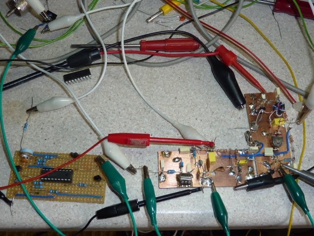
Everything seemed to run OK - I could even generate FSK with the Funky Keyer! However, I wanted to be able to send my call continuously and SLOWLY - so I added a "Beacon" mode to my PIC keyer software and knocked up a little beacon keyer circuit, seen below (at left) with the rest of the beacon-in-waiting...


I downloaded Argo and set up an RF generator at six-and-a-half Megs which, with my 3.579 MHz put me in the ball-park of the beacon section of the 30m band.

Here's the first test run...


For the illiterate amongst you, it says "xpd" - the screen isn't wide enough to fit the whole call sign in at the rate I was sending. I wasn't really "transmitting" - just picking up radiation direct from the circuit - there's no PA, filter, etc at this stage.

The drift in the picture above is down to the old Tektronix RF generator - I hope things will get significantly better when I hook up the USB synth in its place.

This has been fun and I look forward to trying to appear on other people's Argo screens!

...-.- de m0xpd

Update:-

I couldn't resist hooking up the USB Synth...


That's more like it!

Sunday 30 May 2010

The "Radio Times" Amplifier


For the benefit of dx readers, the Radio Times is the UK TV listings magazine which traces its history back to the BBC's original publication. It is distinguished by covering Radio schedules (as well as TV - hence the name) but, just like the other UK listings magazines, it is now full of advertising and editorial nonsense aimed at those who worship the "idiot's lantern" in the corner of the room. I will get round to cancelling my subscription one day!

Regular readers of this blog will remember that I'm a sucker for making printed circuit boards (even when Ugly or similar methods are as good or better). Unfortunately, I used my last sheet of Epson SO41126 Photo Paper in making the S9 Generator. That meant I had to find a new medium for my toner transfer process...

First stop was made during the weekly grocery shop at Sainsbury's new Urmston Store, where I splashed out on a pack of 20 sheets branded "Howard Smith Paper". I should have realized things wouldn't turn out too well when the packaging boasted "environmental glossy photo paper" - the word "mental" was there for all to see!

Here's the "mental" paper (along with the original Epson favourite and some cheapskate paper from Tesco's still to be evaluated)...


Now - I've got nothing against environmental initiatives in principle, but I'm not prepared to substitute concern for quality with concern for the environment (too many disappointments with fair trade coffee, in which the feel-good factor of trading fairly never quite took away the taste).

I don't doubt that the environmental photo paper is great for its intended purpose of bearing photo images - but I found it pretty useless as a toner transfer medium for making PCBs. It was way too thick (at 260 gsm) and - to be fair - it wasn't until I tried it that I realized this is an important parameter for the toner transfer method. Thick card is an unwanted thermal insulator!

Imagine my delight (as a self-confessed cheapskate) when I stumbled upon Alberto's website, where he describes how it is possible to use paper from "junk mail" promotional material, magazines etc as the medium for toner transfer! I just had to try it...

I decided to knock up a PCB for the PA I'd used in the h/b WSPR rig purely to experiment with Alberto's process. I chose two experimental papers; the front page of a recent Radio Times and a flier from Asda.

Here's the toner image on the Radio Times cover...


Never (since the Yellow Pages adverts) has James Nesbitt been so useful!

I also tried the Asda flier (perhaps the fact that I alighted on the wine page was Freudian HI HI)...


Again, for dx readers, Asda is a UK supermarket chain where I choose not to shop - 'nuf sed.

After getting the XYL's iron out, the attempted transfer onto the copper clad board of the toner depicted in the two photo's above yielded disappointing results...
  • "Asda" was useless (why aren't I surprised?)
  • "Radio Times" transferred the toner - but transferred a lot of other stuff too!
After a lot of work soaking and scratching with a pin between traces, I did generate a viable PCB using the Radio Times...


which, when populated and tested, became - of course - the "Radio Times" amplifier...


OK - so Alberto's "free" toner transfer process works - but it took WAY longer than the one hour he promises on his website. That is not to say that it is a bad idea - more experimentation may yield better results with the right kind of paper. Alberto was advocating "cheap" paper - the poorer the better - pity I don't seem to get fliers from Lidl.

I encourage readers to experiment with Alberto's ideas - for my part, I'm going to stick with glossy inkjet paper, despite the cost. I noticed on the web that Tesco have a fairly thin, very cheap paper in their "Value" range (which previously I recommended only for the spaghetti). I am going to give this a try and may report back - watch this space!

...-.- de m0xpd

“m0xpd/garden” operating and the Walkabout Mk II

I guess it all started when I saw Juan, ea5blp’s videos of working CW QRP on the beach on YouTube . I wanted some of that ! It was part of the reason I purchased the nearly-new FT817.

Last weekend I had chance to try (for the first time in my short amateur radio career) some portable (or, at least “/a”) working. I was at my in-law’s farm in Bedfordshire and – in the heat of a glorious weekend that probably will turn out to be this year’s summer come early – I found myself a little table and settled down to see what could be had on the 40m band. It was hardly in the true spirit of /p operating, as I had only flat batteries in the FT817 and so decided to steal some mains electricity from the in-laws!


Those with 20/20 vision will notice that I’m still using my h/b straight key, rather than the paddle I built for /garden working to save the risk of dropping my Bencher. I haven’t worked up the paddle into a robust solution I’d be happy to take on a trip away from home (though I have enjoyed several qsos at home with it).

I was using the Walkabout Mk II antenna which I purchased from the Sandpiper stall at the Blackpool NARSA rally. I have to say, I’m amazed and delighted with that antenna – it really works well with the FT817, as Julian g4ilo concludes on his excellent site, where there’s lots of detail on this combination of Walkabout and FT817.

The walkabout antenna includes a jumper lead to short out the unwanted components of the base inductor. You can see the tapping sockets in the photo below…

I’m going to take this opportunity to record the suggested jumper positions (which came on a piece of A5 paper with the antenna which I’m in grave danger of losing). The table also shows the (approximate) length in inches of the telescopic section, which you need to adjust for best VSWR.


BandConnect 1 to :Length
80m(N/C)48"
40m248"
30m218"
20m348"
17m330"
15m448"
12m437"
10m548"
6m640"
4m622"


You also need to use a counterpoise with the FT-817 / Walkabout combo – mine was a length of hook-up wire. Julian describes a neat idea of using a steel tape measure as an adjustable counterpoise. I guess I’ll give that a try next time I go to the hardware store!

All in all, the FT-817 and walkabout combo worked great mid afternoon on 40m – I had a nice ragchew with Henri, dl4vh, and several other qsos into Europe.

Try it – it is every bit as much fun as Juan’s video implied.

...-.- de m0xpd

Thursday 27 May 2010

H/B WSPR Update

I promised news on performance of the homebrewed DSB WSPR rig - but work has kept me away from the shack for a while. Here, at last, I've snatched a couple of minutes to post a quick update...

After the qsy to 30m I decided to up the power to an obscenely QRO 50mW. I was rewarded by a sold spot by Bruce, w1bw, in MA (5069 km)...


I've had several other trips across the pond with the h/b rig - but the first is always sweetest!

...-.- de m0xpd

Sunday 16 May 2010

QSY to 30m

I enjoyed some success overnight with the new H/B WSPR rig on 40m (Netherlands, Germany, Belgium, Italy) but there are more people working WSPR on 30m than 40m - so it's time to QSY...

I needed a new LPF (the one used yesterday just offers the choice of 80m or 40m), so I looked at chapter 12 of the ARRL Handbook (mine's the 2009 edition - no doubt the shiny new 2010 edition contains the same info) and fired up "Elsie", the filter designer package that comes with the book. Here's the resulting design for a 7th order low pass filter with -3dB corner at 12MHz...


I worked up the filter in LTSpice - along with a parallel filter to check the effects of using preferred value capacitors and "practical" inductors (I think you can do this in Elsie - but I couldn't remember how, so it was easier to use Spice)...


The two simulated responses essentially overlay each other, so I won't waste time and space with a graph.

Whilst we roll our own inductors (and so don't have "preferred" values) we are stuck with an essentially quantized set of inductance values by virtue of the integer number of turns we can put on a toroid (of course, we can mess with the spacing to fine-tune the inductance but, at the "design" stage we have quantized inductance values). I refer to David g4coe's chart in SPRAT 135 when rolling an inductor...


Here's my finished LPF...


The entire rig has now been "smartened up" a bit for the camera...


I fired it up and got an immediate spot from Francesco, hb9afz. More news on my h/b efforts with WSPR to follow...

...-.- de m0xpd

Saturday 15 May 2010

Homebrewed Whispers

I realized recently there's something of a gap in my experience - so I determined to fill it...

Most of my homebrew activities are in QRP rigs for CW. In consequence, I've little experience of generating DSB/SSB signals. Sure - I've played with mixers in receivers - but never in transmitters. That's the hole I decided to plug.

I made a simple balanced modulator, using "Ed" Skelton's circuit as a jumping-off point. Here's the result...


OK - all very interesting - so now I can generate DSB signals, what shall I do with them? I know - I could follow Bill n2cqr's lead and work some DSB WSPR. I have played with WSPR before (both with my Softrock SDR and with my nearly new FT817), but never with a homebrew rig. So - I looked out a little PA I built a while back as a bench amplifier...


I generated a stable local oscillator signal using my USB Synth from SDR-Kits and added a 80/40m low-pass filter (previously built for my HEXFET PA Brick for the SDR) to keep my emissions clean. The whole lash-up is seen below (I've added some labels so you can spot all the elements!)...


I measured the output on the 40m band as 20mW (13dBm) and set up the WSPR station details accordingly.

Delighted to be received almost immediately by Jaap, pa0o, in Zuidwolde, Netherlands...


This really is whispering - homebrewed rig, 20mW output (10mW really, given that my lower sideband is just somebody else's QRM) - great fun!

...-.- de m0xpd

Friday 14 May 2010

"Original, Celebrated & Curiously Strong"

I couldn't help myself - I just had to do it...

There was nothing wrong with the Ugly S9 Generator, but I couldn't resist making a PCB.

Actually, I do prefer "keeper" circuits to be on a PCB, as I think they're more robust - they survive dropping, without bending wires into accidental shorts. What's more, I enjoy making PCBs!

So here's the design, produced very quickly in EAGLE...


And here's the resulting PCB...


It was easy to populate with parts found in "stores" (the "up-market" end of the junk box) - excepting the PCB-mounting phono socket I had to buy from Maplins for £1.39 (HF99). Inveterate readers of this blog will remember the switches from the homebrew attenuator project - I snapped up a job lot from Peter, G7JAB at the Rishworth G-QRP convention.


You will have noticed that the corners of the PCB have a nice radius - carefully chosen to fit in the traditional "Altoids" tin - here is the assembled generator...


This is the first thing I've made in an Altoids tin - it taught me some interesting lessons, not unlike those you must learn to make a ship in a bottle! I'm not sure it is worth the trouble, but it does look "cute"...


In the end, I used a 36 dB attenuator in this version (once again using Alan, vk2zay's excellent calculator) - which gives me S9 and S3 - and I've fitted a 3.579 and a 7.030 MHz crystal. The original NorCal design has four crystals, but I didn't have any 4-way switches in stock!

...-.- de m0xpd

Tuesday 11 May 2010

Intellectual Property Theft and the S9 Generator

Whilst trying to make the Not-so-superhet (Blogs passim) slightly more super, I decided I needed a stable, defined RF source to feed directly into the antenna. I have used my Wobbulator with some success - but that, of course, is at IF and I wanted to test operation of the entire receiver.

Fortunately, those nice guys at the NorCal QRP club have a design for a simple generator, which produces s9 and s1 signals at any frequency for which you have a crystal (up to the 15m band). Although the NorCal unit is produced as a kit (currently listed as "Out of Stock") they also make the assembly manual available online for download - including a circuit diagram!

It won't surprise readers to hear that I made a pirate copy or, to make it sound less like IP theft, a "replica" - here's the breadboarded version for initial mock-up...


I then made an ugly version, which is slightly more practical...


The (very) ugly circuit board sits atop the PP3 which powers it, has a socket into which the chosen crystal may be plugged, a BNC output and a switchable attenuator, to select s9 or s1.

The NorCal documentation suggests that it produces s9 and s1 - but actually their design produces s9 (50 microVolts) and 1 microVolt (which is between s3 & s4 - NOT s1).

You can find a really nice table of the S levels at the G-QRP website.

I decided to build a 48 dB attenuator (rather than the 34 dB pad in the NorCal design), to give me s9 and s1. This pi attenuator was designed using Alan, vk2zay's excellent resistive pad calculator (Alan's website isn't responding as I write, so I'll add the link later).

I tried the unit into the nearly new FT 817 (as it has a hugely convenient front antenna socket!) and - sure enough - I get s9 and s1. It "does what it says on the tin".

I like the NorCal design - especially how the LED is used as both a "power on" indicator and a "voltage reference"! I think I'll make a PCB version, to make it more rugged and I may even mount it in an Altoids Tin.

I hope they won't mind me plagiarising their circuit - my first rig, which I still have, was a NorCal 40, so I am a customer of sorts (to tell the truth that was purchased second hand).

...-.- de m0xpd

Saturday 8 May 2010

Audio Repair

The "number 2" audio system hasn't been working for the past month or so, but life has been too hectic to sort things out. Things came to a head this week when the XYL wanted to listen to something and couldn't, so she booked me in for some audio repair work!

I should explain ... the "number 2" system is what you might call classic British Hi-Fi (except for the Sony CD player used as source). There's a Quad 33 Control Amplifier and matching FM Tuner, exquisite Goodmans LS3/5As, a collection of Quad II power amplifiers (which don't get used very often) and a pair of Beam Echo Avantic DL7-35 amplifiers, one of which is at the heart of the fault that set the XYL complaining.


[The "number 1" system is what you might call "pro audio", based on Genelec 1031As - to be honest, I prefer listening to the number 2 system!]

The fault was a loud intermittent buzzing, which sounded like a supply fault to me - but all the mains cabling seemed OK - so the left channel's amplifier was removed to the bench...


The DL7-35 is a "commercial version of the Mullard 20-watt amplifier of which full details were given (...) in three articles in the Wireless World by W. A. Ferguson and D. H. W. Busby" (extract from a review in The Gramophone, October 1956). It uses an EF86 Pentode input stage, ECC83 as phase splitter, driving a pair of EL84s in Ultra-Linear configuration. Expecting that I would need to look inside the amplifier, I took off the top cover and connected an input and a load...


(you can't see from this angle [as it is hidden behind the choke] but I had previously replaced the output stage biasing cathode resistors (470 Ohm), along with new capacitors under the chassis)

The amplifier worked perfectly in a one hour soak test - so this must have been a mains wiring fault/intermittency, as I first suspected (indeed, some of the screws in the Bulgin AC supply plug were loose - they were closed onto solder-tinned wire ends and this is known to be bad practice). So - what started off as anticipation of a pleasant few hours messing with a valve amplifier, turned into a trivial opportunity to dust and photograph some of my collection!

Here's the pair of DL7-35s in situ atop the "Billy" corner unit (that loosely inspired last week's "Shack Furniture" project)...


Apart from the extraordinary levels of dust (HI HI), you can see the new phono input sockets I fitted (in addition to the original phono input connector, there used to be a paralleled "TV Antenna" type input socket and an input potentiometer, all of which I scrapped in the original restoration). The chassis of both amps has lost a few chips of paint here and there and the rust worm has made its presence known - but it isn't bad enough to re-finish the amps. To the extreme right, you can just see the first of the line of Quad IIs, which are on display along the rest of the bookcase.

So - now that's sorted, I wonder what to do with the rest of the weekend.

...-.- de m0xpd

Wednesday 5 May 2010

Shack Furniture

The m0xpd shack has always been a ramshackle arrangement (much like the rest of the qth) but things were coming to a head recently, with no room on either the workbench or the operating position. Too may bits of projects on the go, too much junk never packed away (not that everything has a place to be packed into), too much shack clutter.

You can see what passes for the workbench here...


and the adjacent operating position here...


Fortunately, some weeks ago, the XYL's place of employment was having a clear-out, which involved getting rid of some old shelves. They were to be taken to the tip - but the XYL recognized the "salvage" potential and brought them home as a gift (she knows how much I resent the price of timber). About 60 feet of 18mm mdf shelving, with no holes or marks, all nicely cut to uniform width (approx 1 foot) and length (approx 4 foot). What a find!

I decided to use a few lengths to do something about the shack - so I biscuit-jointed some of the lengths together to make wider panels, cut out the pieces (to a design which owes something to Ikea's "Billy" corner unit), routed some slots in the end-pieces to take the shelves and joined it all together with polyurethane glue. That was the assembly I was having trouble with at the weekend - I gave up dodging the showers in the end and did the glue-up on top of the table saw!

Here's the result (too excited to finish it off at this stage)...


You can see the "trusty, rusty" FT 101ZD on the bottom shelf, tuner, SWR meter and antenna switching next up, a converted Key PMR rig (just in case I ever fancy a little erudition on 2m HI HI) with the FT 817 nd (Blogs passim) atop and the Funster Plus aside. On the top of the unit are the Not-so-superhet (along with its inverter HT supply) and the Paraset (right).

Beneath, the h/b straight key, the Bencher Paddle and the Funky Keyer (still swollen with pride over its recent coverage on Soldersmoke) all find shelter.

I intend to face all the visible edges of the mdf with real timber and I might even paint it - but that will be another day - don't hold your breath!

...-.- de m0xpd

Sunday 2 May 2010

Mouse Paddle

Poor weather this May Day Bank Holiday Sunday afternoon has kept me in the shack. I was doing some woodwork and the glue-up was so big it needed to be done outdoors - but the skies looked ominous, so I left it for another day...

Recently I've had some fun with the FT817 (Blogs passim) and the Walkabout Mk II antenna in the garden, but I was a little uneasy carrying the Bencher paddle down there - so easy to trip and drop it.

I've been drooling over the nice little "Mini-Paddle" from Palm Radio, but I've still not recovered from all the exertions of opening the m0xpd wallet on too many recent occasions, as documented in these pages, so I haven't yet taken the plunge. Still, I do need to do something about a paddle for /p (or, at least, "/garden") working.

Thoughts turned to all the goodies I had harvested from the recent cull of mice in the m0xpd shack - especially those micro-switches...


I figured I could lash something together using the switches - particularly as I had already once used a mouse as an input to my Keyer, after the style of kb1jqx.

A couple of hours messing about with a scrap of Veroboard yielded a servicable paddle...


Don't get me wrong, dear reader - this is just a bit of fun - the result of hiding from the drizzle on a Sunday afternoon!

The paddles themselves were filed out of copper-clad glass fibre and they are "hinged" using solder tags.

The h/b "mouse paddle" will never displace my Bencher...


... but it has a surprisingly good "feel" and, to prove its viability, I've just enjoyed QSOs on 80m with two fellow FISTS members, g3xzx and gm3jud, using the paddle. Although these didn't quite reach rag-chew proportions, they were in a different league to the terse exchanges the contest boys have been filling the 40m band with today.

Whilst the "mouse paddle" above is little more than an experiment (in fact, little more than a joke) it has whetted my appetite to try making a small paddle - I have previously made a straight key, which I use pretty much every day (it was a great excuse to get the knurling tool out)..


Bencher, Kent, Begali - watch out HI HI

...-.- de m0xpd

Saturday 1 May 2010

CW Machine

I mentioned in an earlier blog that, in my view, the FT817 needs an IF filter to be useful for CW (without it, it doesn't match my Funster Plus on 40m).

Well - I'm pleased to report that I now have one - and that it works a treat!

Regular readers won't be surprised to hear that cheapskate/"tightwad" m0xpd was depressed to see the prices for CW filters, some of which (taken from the 'net today) are shown below...

SupplierCost
Radioworld£109.95
Martin Lynch & Sons£118.48
Waters & Stanton£89.95
W4RT$114 + Shipping


However, Julian, g4ilo, commented on this blog that Jim, k8drn, supplies filters at a very competitive price. I contacted Jim, who quoted $110 including delivery to the UK - so I placed an order!

The fall-out from Icelandic volcanos introduced a little delay into the delivery, but the part duly arrived, in good protective packaging (the XYL has her eye on the nice tin)...


The filter board itself...


is very easy to plug into the main board of the FT817, following the instructions in the Operating Manual...


(in fact the only difficulty was figuring out how to re-fit the Palm Radio "Peg Leg" tilt stand kit on my FT817).

All seemed OK on the mechanical side - but when I tried to use the filter for the first time I came unstuck.

The Operating Manual instructions (page 74) told me to ...

"Change the setting of Menu #38 (OP FILTER) to "SSB" (if installing the YF-122S), or "CW" (for the YF-122C/F-122CN).

When I tried this, there was no audible change on setting CW and an audible change on selecting "SSB" - this audible effect threw me!

Here's a snapshot of the spectrum of the audio from the FT817, in CW mode at the high end of the CW segment of the 40m band this morning, with Menu #38 in "OFF" mode (captured, for convenience, by CWGet)...


It shows wideband noise (- the wide-open response which is exactly the reason the CW Filter is needed). When I selected "CW" in Menu #38, exactly the same noise spectrum was heard.

When, however, I selected "SSB", the following signal was produced...


This noise has been filtered by exactly the expected bandwidth - but at the wrong centre frequency. I was confused!

Thankfully, Julian g4ilo came to my rescue, sending this link to some clear step-by-step instructions by Dave Fifield, AD6A, for filter installation. Fortunately, these go one VERY IMPORTANT step further than the instructions in the Operating Manual - and sorted my problem. Dave's key final step taught what I had failed to spot: that it is also necessary to select "NAR" in row 7 of the function options "buried" in the "A,B,C" buttons.

Here's the resulting 40m noise spectrum (indicating the expected frequency response of my new filter)...


That's better! Thanks Julian! Thanks Dave, ad6a!

I gave it a try with a quick qso with a special event station, gb0fsg, "Celebrating 100 years of Fochabers scouts from Inchberry near Fochabers", operated at the time by Don.

I continue to be really impressed by the FT817 (though not by its Operating Manual).

Now I am also very impressed by Jim, k8drn's filter - great service, great product, great price.

Thanks Jim!

...-.- de m0xpd