Monday 28 June 2010

Homebrewed WSPR and a right royal stuffing

What a weekend!

Having covered QRSS, S/MT Hellschreiber and WSPR, the logical progression for the 30m beacon project (Blogs passim) seemed to be generation of WSPR signals without the safety net of the PC. I realized that WSPR is just FSK (which the beacon is well capable of generating), but I also knew that timing is more of an issue for WSPR. I needed to be running synchronously to true time (within a second or so) rather than free-wheeling, completely oblivious to the clock. So - I decided to have a poke about on the 'net to learn from others, before trying to make something original.

I quickly found Gene w3pm's WSPR Projects page , where he publishes an interesting design for a PIC-based WSPR generator and kindly gives full access to the source code - an ideal place to begin to learn the "nuts and bolts" of the WSPR signal.

Here's my lash-up of the signal generator...


I followed Gene's original words and music fairly closely - substituting a 4066 for the 4016 specified, replacing the 2n2222s with my trusty 2n3904s (due to supply chain issues in the junk box) and replacing the transformer-coupled output (for similar reasons). You can see the RS232 interface to a PC (also used as an NMEA interface to a GPS system) on the left, the 16F628 PIC and 4066 analog switch next and the VFO to the right. The system seemed to work well enough - but it needed a few levels of "calibration" and needed to be loaded with the correct data for MY WSPR message - my call, locator, etc...

The first stage of calibration is setting the 4MHz clock for the PIC, from which the system derives all timing (and, thereby, stays in sync with the network of nodes on the WSPR network). This was achieved by tuning the nearly-new FT817 to 3.9995MHz in USB mode and looking for a 500Hz output. Yes - I do have a counter-timer, but it is difficult to avoid loading the crystal oscillator with test clips etc, so the "wireless" connection was preferred!

Next step was to "calibrate" the FSK intervals (WSPR uses 4-FSK with a spacing of 1.465 Hz between each signal frequency). I found that the nominal resistor values in Gene w3pm's schematic gave way too high a frequency change - so changed to higher value resistors until the delta Fs were about right.

Once all the levels etc were right, I had to encode the WSPR message - which consists of a sequence of 162 characters, each representing one of the four allowed frequencies that constitute the 4-FSK signal. Into these 162 characters are encoded the callsign, the locator and the power level. Stu Phillips EtherGeist blog gave me the head start I needed - pointing me to the command-line version of WSPR, which can generate the message as text...


I copied the central "symbol" column of this text (containing the integers 0-3) and rearranged them (using MATLAB) into a text file, with the additional code "00+" signifying the end of the message...


This could then be uploaded into the breadboarded system using HyperTerminal...


All looked well, so I tried a direct connection to the sound-card of the shack computer on which I run WSRP and - sure enough - I could decode the message...


There is some evidence of 50Hz harmonics from a "hum loop" problem but - apart from that - all was fine. The PC went on "receiving" the "transmissions" from the new WSPR signal generator all afternoon (it is programmed to transmit on one 2 minute segment every ten minutes).

Flushed with this limited success on Saturday, I set off on Sunday with a spring in my step and designed a PCB in Eagle...


... but then disaster struck.

First, England were scheduled to play Germany in the round-of-sixteen in the World Cup and - like a fool - I had agreed to watch the game. Let's just say I would have had a much better time carrying on with the radio project than watching a bunch of lazy, overpaid primadonnas being forced to concede that there is precisely nothing "premier" about the "premiership".

Second, the shack computer suffered a noisy crash - sounded like a mechanical fault in the hard disk that is going to require replacement.

Anyway, despite these annoying set-backs, I did manage to get a little more done on the final version of the system before running out of weekend...


Perhaps next week I'll get it on the air and hook it up to my old Garmin eTrex GPS system, so I don't need to worry about timing quite so much.

...-.- de m0xpd

Tuesday 22 June 2010

Mea maxima culpa

OK guys (that's a gender inclusive "guys", if I'm fortunate enough to have attracted any readers from the fairer side) - I goofed.

I left you with news that the new beacon receiver hadn't enough audio gain. After a few moments poking about with a 'scope probe and an audio oscillator I was forced to admit the truth. I'd made a mistake (at the schematic capture stage in Eagle) which had inadvertently swapped the inverting and non-inverting inputs of one of the op-amp stages. It was a miracle the system "worked" before at all - but work it did - I showed you the spots to prove it!

Having tracked down the error, I was able to pull off the changes on the PCB (requiring surprisingly little "butchery") and so we're back in action.

I came into the shack this evening and heard a lot of activity on the 30m WSPR segment - but was getting no spots.

Ironically (given my earlier comments) I had now set the AF gain TOO HIGH (!!) - so I needed to back off the gain setting trim pot just a little.

Now the spots are coming in nicely...


I can't leave the receiver running all night (some guests have the temerity to interpret the shack as "the guest bedroom" and won't be happy with the PC fan noise) but I'll post an update of catches during the evening if there's anything to be pleased about.

...-.- de m0xpd

Saturday 19 June 2010

Beacon Rx

I have now had plently of fun transmitting WSPR and QRSS signals on my homebrewed beacon-in-the-making. Now it is time to do some receiving...

To be honest, I think those who only transmit are much to be despised (hyperbole for effect). We beacon experimenters owe a debt of thanks to those who spot and grab our signals - in my case that's a particular thanks to Guenael and Johan and others - and the best way to repay that debt is to play our own part in the reception and reporting of the signals of others. This is, after all, a street with two-way traffic!

So - I decided today was the day to cook up a receiver for my beacon.

I took as my jumping off point the excellent DC receiver section of Roy Lewallen, w7el's, Optimized QRP Transceiver for 40m . I had already enjoyed success with this circuit, having used it as the basis for the receive side of my Funster Plus rig. Now all I needed to do was modify the AF filter to give a passband in the 1.5kHz region associated with WSPR signals...

This was quickly achieved with an LTSpice model...


which offered the required frequency response...


Now I've got the "free" toner transfer process down to a fine art, it is (almost) simpler to go straight for a PCB, rather than mess around with any other processing method - so EAGLE gave me a layout in no time...


but is still took an AGE to drill all those pesky holes...


Once the board was stuffed I was too excited to make tests or anything as organized as that - I just connected up the minimum set of elements on the bench and took it for a test drive...


You can see the new Rx board at left, with the Si570 USB Synth above it and the Low Pass Filter connecting to the antenna at right.

Here's a closer view of the new Rx board doing its thing...


Sure enough, I started spotting WSPR signals - the first from pa2wo.

The AF gain of the receiver isn't high enough - I can only get an Rx noise level of -25dB on the WSPR screen at the moment, but it still pulled in some signals...


I'll leave it running overnight and see what I can catch - despite knowing that the overall gain isn't high enough yet. Perhaps I'll sort that out tomorrow.

...-.- de m0xpd


Update:

As promised, I left the receiver on overnight with the following results (ten different stations, all spotted in the evening (nothing after 22:15 UTC)...


Not very impressive! I must try and make some improvements today - but first I've got to fix the bottom of the workshop door, which is showing signs of age!

Thursday 17 June 2010

More on the Mag Loop

A spell of summer weather has made it impossible to stay indoors - so I could re-visit work on the experimental loop antenna.

After the initial prototype, which tuned up only on 40m, I'd made v0.2 with a 0.7m diameter to tune on the 30m band...


In addition to the smaller resonant loop, I experimented with a few sizes of driven loop and came up with the optimal relative size you see above. I also added a long shaft to the tuning capacitor and a knob (seen at top left), so I could tune the system without too much trouble from hand capacitance effects.

I tried the QRSS beacon on the loop last evening, but was disappointed with the results. First problem wasn't the loop's fault, but it was an annoyance - a loss of frequency stability.

There was a 5 - 10Hz variation with something like a one minute period. I could see a few possible explanations for this...
  • poorer earthing than on the bench
  • thermal effects (heating from sun and shadow, cooling from breezes, etc)
  • sitting in the RF field of the magnetic loop antenna
...but I haven't yet had a chance to isolate the actual cause. Suffice to say that when I brought the beacon back into the shack, the frequency was rock solid again.

Aside from the irritating drift, the radiation from the entire beacon/antenna system was pretty disappointing, with only a very tenuous spot on Peter, pa1sdb's grabber. I was used to hitting most of the European grabbers when the beacon was driving the g5rv, so I began to suspect the magnetic loop wasn't up to much...

Today I had chance to make a few measurements on the antenna. I found the loop was tuned such that VSWR was about 1.25 at the 10.140MHz frequency the beacon had been working - that should have been OK. Mind you, all a VSWR reading proves (if it is done properly) is that power is going into a system - it doesn't confirm this power is being radiated out as nice radio waves! I decided I'd try to use the loop with my nearly-new FT817 on 30m CW, to find out if the loop could actually radiate...

I tuned the loop for 10.106MHz (by listening for the maximum noise output from the receiver, rather than the more formal tuning methods used before) and then measured the VSWR around this frequency...


All looks fine - but you can see just how narrow the tuning is.

The antenna clearly was working well on receive (I heard a SOTA activation by la8bca/p and a flurry of resulting traffic) and so I tried for a qso. Anders, sm2ecl, called CQ and he gave my answer a 549. Anders was using a loop as well - but he was driving his with 100 Watts as against my 5. I followed with a weak contact with Ludi, ok1has.

So the experimental loop antenna isn't just a dummy load, after all!

...-.- de m0xpd

Sunday 13 June 2010

Pretty in Patras

The weather has been too bad to permit of further developments on the magnetic loop antenna (not strictly true - I have made v0.2, which has a 0.7m diameter main loop and does resonate in the 30m band - but the weather has prevented any outdoor testing). Accordingly, I was looking for something to do in the shack...

Yesterday, whilst strolling around Tesco, I slipped a laminator into the trolley...


The model number is H0L09 and I paid about £21 (there is a cheaper "Tesco Value" laminator at around £15, but the model I chose offers hot or cold laminating and a release feature - which, I figured, meant that the roller spacing can be changed - important when you're trying to squeeze thick PCB through the machine!)

Anyway, this afternoon I decided I'd see if it makes PCB production any easier - with GREAT results!

I decided to give Alberto's junk-mail paper stock method another try, this time chosing a page from the Patra summer catalog. Patra is a sort of up-market Cotton Traders. I don't know if the name derives from the eponymous city on the Peliponese (where my friend leads the Audio Group of the Wire Communications Laboratory) but the catalog is full of pleasant images of even more pleasant YLs, many of whom have dark hair and look as if they could hail from Greece.

I prepared a trial PCB pattern (actually the layout I'd made for Francesco, ik3oil's Frequency Counter, as previously used in my Funster Plus ), cleaned up a piece of copper-clad board and passed it through the laminator.

It goes through smoothly enough - but the machine does emit a few groans and sighs during the process!

I didn't count, but I guess I passed the board through twenty times, before putting it in a cold water bath. Sure enough - just as Alberto promised - the paper soaked away cleanly, leaving a PERFECT transferred pattern. Most wonderfully of all, there was NONE of the irritating "chalky" deposit between the traces that has compromised so many of my recent attempts at PCB manufacture. In fact, THIS IS THE CLEANEST, SIMPLEST RUN THROUGH THE TONER TRANSFER PROCESS I'VE EVER ENJOYED.

There were some "paper fibres" left on the toner, clearly visible in the photo below...


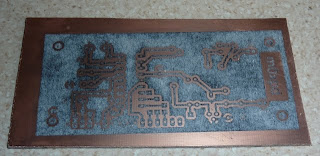
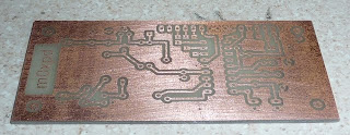
... but this is irrelevant to the final quality of the board, which is seen here after etching and trimming to size (I've still got to drill all those pesky holes)...


To be hyper-critical, there is a tiny degree of "porosity" in the ground-plane (but I think selecting a thicker layer of toner in the printer settings and - perhaps - a few minutes less in the etch bath - will fix this). That aside, this is a really significant improvement in the m0xpd PCB process.

Thanks to Alberto.
Thanks to the Tesco Laminator.
Thanks to the pretty girls of Patra.

...-.- de m0xpd

Magnetic Loop Musings

The trouble with all the recent fun and games with beacons (Blogs passim) is that the station antenna tends to be monopolized - with the result that "ordinary" operating suffers. I decided I needed to think about a dedicated beacon antenna...

Recently I read a nice nugget of wisdom concerning antenna design: you can have any TWO of the following desiderata, but not all three...
  • small size
  • high efficiency
  • wide bandwidth
This set me thinking - I don't need any bandwidth for an antenna dedicated to 30m beacon working - it is almost transmitting a monotone!

After recent success with the Walkabout base-loaded whip, I thought about making a shortened dipole with two similar elements. However, I realized there's an important category of antennas of which I've no experience - magnetic loops. These can follow the rule by being small, efficient and (as they're deliberately tuned to one frequency) narrow bandwidth. I set about making one as a learning exercise...

The prototype was made with "available materials"; 8mm microbore copper pipe, scrap timber, odd pieces of clear sheet polystyrene, a few cable clips and an old 115pF variable capacitor from the junk box...


Here's a close-up of the driven element...


and here's the tuning capacitor...


I could study the tuning of the experimental antenna in two ways; sweeping it with my g3wpo dipper (fast and approximate)...


or via estimates of relative input impedance using my Return Loss Bridge (seen at the right hand side of this photo - VERY slow yet precise) ...


The antenna did, indeed have a single resonant frequency and it was amazingly sharp! Unfortunately, the resonance was too low (running from just below the 40m band to around 9 MHz). If I had been bothered to do the math before throwing the prototype together, I would have been able to predict this...

The inductance of a single, circular turn is a standard result (Claudio, in3otd, has an on-line calculator) and the variable capacitor had "115pF" conveniently penciled on one of the vanes. My prototype loop (which felt as if it ought to be "about THIS size") turned out to have a diameter of 44 inches (1.117m).

Using the equation...

...predicts a resonance at 7.89MHz (I've no idea of the provenance of the 115pF label on the cap, and I haven't accounted for parastics, mutual inductances, etc). The predicted result agrees pretty well with observation - the tuning is "good enough for jazz".

Reducing the value of the tuning capacitor increased the observed resonance in the expected way, but the Q started to drop as I went over around 9 MHz - so I'll try making a smaller main loop. I need something that will go through the hatch into the attic after all HI HI.

...-.- de m0xpd
Saturday 12 June 2010

Bolstering the Beacon

Having received pleasing reports for the 30m beacon, it was time to consolidate a loose affiliation of components on a breadboard into something a bit more permanent. I also fell victim to the dreaded "specification creep" and decided to make some "improvements"...

First, I wanted to improve stability of the VXO, so I added a regulated power supply to the oscillator stage. At the same time, I realized it would be easy to kludge together a "power down" option for the VXO - no need to have it pumping out a signal (particularly one in the 80m band) when the beacon is running in WSPR mode.

Here's the revised VXO, which certainly doesn't deserve to win any prizes for circuit design - yet has the attractive property of working rather well!


The 2n3906 implements the brute force power-down and the two stages before it are about level conversion from the ~12V circuitry to an active high (5V) control line for the PIC.

The beloved EAGLE produced a pcb design, which was quickly translated into copper. Drilling the myriad holes in a pcb like this is by far the most tedious part of the process...


... perhaps I'll get into surface mount!

Anyway, to cut a long story short, a new PCB takes the stand-alone beacon idea one step closer to reality - here's the VXO in detail...


and here's the balanced mixer - I hope you like the technicolor tri-filar windings on the toroid...


The whole system, seen below plugged into the band-pass filter and Si570 USB Synth (Radio Times amp and LP filter are off to the right) does indeed offer the sought-after improvement in frequency stability on-air...


The loop-back seen at the bottom right corner of the board is where I will have option to switch in the "IF" signals associated with my DSB WSPR Station when I get around to it - all I need is a 2 pole change-over switch; one pole to select the appropriate IF signal and one to signal to the PIC to power down the VXO (when in WSPR mode). I've retained the in-circuit programming interface (at top left) so I can plug in the PicKit2 programmer/debugger and make software changes.

Notice how useful blobs of Blu-Tack are in stopping wayward circuit boards skating all over the bench.

Next steps include...
  • remembering how to power up the USB Synth locally (so I can completely sever the funiculus umbilicalis from the PC)
  • putting the whole shooting match in a box of some kind
  • setting up a dedicated beacon antenna to free up the main station g5rv

...-.- de m0xpd
Sunday 6 June 2010

Red Roses and the HW7

Had a nice morning at West Manchester Radio Club's Red Rose QRP Rally today.

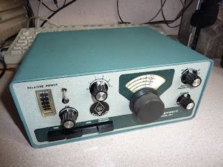
I couldn't resist an old Heathkit HW-7 which I picked up for a good price...


The rig is clean enough and works well (although there is a contest on 40m this afternoon, so I didn't bother trying for a qso - I'll get around to that when things quieten down a bit). It has the Jack Clennon, g4zqk, mods (SPRAT 59, page 17), which seem to work rather nicely.

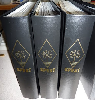
Talking of SPRAT, I visited George g3rjv and his colleagues on the G-QRP stand and got some binders for the journal...


I've been after these since Rishworth last year - by the time I got to the stall that time, they'd sold out! I only joined G-QRP when I was first licensed (as m6pad, back in 2008) but, thanks to a kind gift from Tom, g0myn, my hard copy collection of SPRAT stretches back to 2001.

Of course, I've got the CD - but there is no substitute for the real thing. Now I guess I'll spend a pleasant evening leafing through back issues...


More reports on the HW-7 when I fire it up in anger.

...-.- de m0xpd

Saturday 5 June 2010

New Beacon on the Block

I'm pleased to be able to report progress on the QRSS Beacon project ...


I had managed to get some nice clean FSK Morse signals last week, but decided to make a more complex keyer/controller device. The idea was to augment the "open collector" output of my usual PIC keyer by adding a voltage output, which would directly control the VXO with high-resolution signals. The motivation for this increase in complexity will be seen later - read on...

I took the opportunity to port the code from the PIC16F84a (a choice which has its origins in Eamon "Ed" Skelton, ei9gq's PIC keyer in RadCom (Vol 84, No 12)) as I was "running out" of 16F84s! I have quite a handful of 16F676s in "stores", so that was the target platform. I also found a few MCP4922s - 12 bit D/A converters from Microchip and used one of these as the D/A converter to generate the control voltages. Yes - they are massively over-specified for this application, but they're easy to use (much more so than knocking something together from resistor ladders etc) so, in a strange sort of way, I am "keeping it simple".

Here's the lash-up of the new controller - made on a "breadboard", as it it more convenient than (e.g.) ugly methods for DIP packages and there are no high frequency issues to contend with - even the PIC is clocking very slowly...


You can also see my PicKit2 development programmer / debugger, which I use to program the PIC, the VXO and mixer (forming the "L" at bottom right) and the Si570 USB Synth (top right).

The PIC (the DIP package in the middle of the breadboard) "talks" to the D/A (further right) through an SPI interface, which I implemented in the PIC using some "brute-force" coding (the 16F676 doesn't have anything as sophisticated as serial output). I also took the opportunity to add a control line and some circuit modifications to the VXO which allows the PIC to mute the entire system.

With this enhanced control of the VXO, I could do more than just send FSK morse code - particularly, I could send S/MT Hellschreiber signals.

I set about designing a font for Hell characters (at least those in my callsign) and wrote some code to allow the new controller to send my call - here's the first try (monitored locally on Argo and before I'd implemented the "mute" between characters)...


Here's the result with the system generating FSK Morse and S/MT Hell sequentially, with the glitches between characters muted out...


This morning, I connected the system to a 10MHz Bandpass filter, the "Radio Times" amplifier and the 10MHz LowPass I'd used on the h/b WSPR beacon and fired it up...


The BandPass filter was built to lose the unwanted lower sideband (which, given my target frequency of 10.140 MHz and the 3.579 MHz xtal was going to be at ~6.5 MHz).

I measured an output of 150mW into my half-g5rv.

I was delighted to see myself appear first (as the faint signal towards the bottom right of the screen) on Guenael's grabber...


and then on the on5ex grabber in Belgium...


Here my signals are clearly seen, just below Bill n2cqr's "not-so square wave".

I was taking up too much of the spectrum, but (given the PIC programmable controller) adjustment was a simple matter of changing a few constants in the program. My FSK now only occupies 5 Hz or so.

This has been great fun and I look forward to seeing where else I can send my new Hellschreiber signals.

...-.- de m0xpd


Update(s):-

Guenael Jouchet spotted my signals and put a report on his QRSS Reports page (see Guenael's comment below).

Francophones should visit Guenael's excellent "It's Raining Elephants" blog (well, everyone should - but if you can read French or arrange a translation you will get more pleasure from your visit!)

Johan, pa0tab, also spotted me on his "Tabber" grabber at locator JO33hf and kindly sent a report.