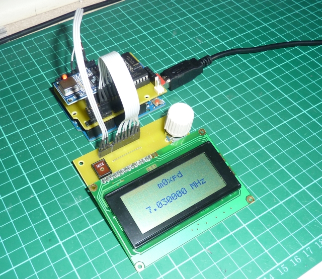
Meet my new rig - a QRP CW Transceiver for the lower HF bands, built around the
Arduino "open-source electronics prototyping platform".
Readers have seen in recent posts how I developed a
multi-mode beacon using the Arduino - but that was only a waypoint on the journey towards a full ham radio transceiver.
We started the journey with my homebrew version of the Arduino - the
"Wotduino" and then wrote code to make the Wotduino work as a
Keyer. Then the Wotduino was given the ability to generate radio frequency signals, using an AD9850 DDS chip on an inexpensive module from eBay, mounted on a
homebrew DDS shield. Then we added a QRP transmitter, enabling the system to work as a beacon. The last leg on the journey is a receiver, as seen in the photo above.
My new receiver is derived directly from the Rx stage of Roy Lewallen, w7el's beautiful and definitive
Optimised Transceiver for 40m.
I've used this as a start point before, both in the Rx for my
"Funster Plus" rig and as a
QRSS/WSPR receiver.
My new circuit is implemented on an Arduino shield, as seen below...
The signal path from the antenna goes to a double-balanced modulator, where it is mixed with the LO signal from the DDS module. This generates audio frequency (by direct conversion), which is amplified in a common base stage and then passed through a 2nd-order Sallen-Key bandbass filter. Next, a further gain stage controls volume and limits the voltage swing (ironically using the same back-to-back diode method exploited in the
Tube Screamer). The receiver is muted during transmission by a FET pass-gate, under the control of the Arduino. Finally, a little audio power stage drives headphones or small speakers.
The receiver sits in the stack of "shields" on top of the Wotduino...
All this adds up to a viable transceiver, as explained in the block diagram of "architecture" below...
The Wotduino controls everything through what we might call a "control bus" formed by the stackable header plugs on either side of the boards.
To this bus is connected a paddle and a straight key, interacting with the
keyer code. The DDS module also sits on the control bus, through which it is instructed to generate the appropriate frequency. This RF is carried on an additional "RF bus", implemented on a line of 6-way stackable headers which link the DDS, Tx and Rx shields. The DDS signal is amplified and buffered by a circuit on the Tx shield, from where it is passed to the new Rx shield by another line on the RF bus.
Also hanging off the control bus is a display to show the operating frequency. This is an old 12-character, 7-segment serial input LCD module which I picked up at some long forgotten rally for pennies.
The frequency is adjusted using a rotary encoder - which also selects the band. The rotary encoder has a push-button, which allows me to adjust the frequency in 10Hz, 100Hz or 1kHz increments (10Hz is the lowest resolution necessary, whilst 1kHz lets me scan across the band - or change bands - quickly). When you adjust the frequency above the top band edge (
more exactly above the top of the CW segment of the band), it automatically steps up to the next band. Similarly for downward QSYs.
Here's the rig in the habitual lashed-up state (perhaps I should say
"Kludged" or "Kloodged" state) on the bench, back in the day when I was still using a potentiometer for frequency adjustment...
It is connected to speakers from a roadkill computer and an old straight key for testing.
I don't know about you, but whenever there's a viable rig testing on the bench, I just can't keep my hand off the key and the antenna coupled to a dummy load - I always end up having a QSO. So much for testing!
In spite of all my high intentions of making a case, etc, etc, I couldn't stop myself from answering Andy dm5mu in Leipzig and getting a 559. Then Miroslav, yu1dw, in Cicevac, Serbia for a 579. Not bad for my first two attempts on 40m with my 500mW.
After these initial QSOs I added a "send/return" connection so I could route the audio signal through my
variable bandwidth CW filter (SPRAT v.146 p20), which makes the rig much easier to use when the bands are noisy or congested.
The rig is set to cover top band through 20m - but so far I've only had QSOs on 80 (including Ian, g3roo's QRSnet) and 40.
Right - now let's see about some kind of enclosure to pretty the whole thing up a bit...
...-.- de m0xpd