Saturday 26 April 2014

RF Sweep Generator

Here's some notes about generating RF sweep signals on the Arduino for filter testing - it is really just a digital version of the old Wobbulator concept.

First look was a little disappointing because, whilst I had recently satisfied myself that the DDS modules can have their frequencies changed very quickly, (in fact, I showed that the Arduino Due was capable of changing the frequency of an AD9850 in 9 microseconds ) the humbler Arduinos turned out to be rather slower.  Specifically, I found that a simple loop of code involving just writing a frequency to the DDS and incrementing the frequency value itself took 950 microseconds (Arduino MEGA + Soft SPI interface to AD9850). This was imposing a surprisingly low “sample rate” on my plans for a digital “Wobbulator” before I’d even got started.

I wanted to be able to measure the response of crystal filters – so I needed a filter to measure.

I started off with a Spice model, constructed in the wonderful LTSpice package from the good folks at Linear – wonderful not only ‘cos it is FREE but also ‘cos it now works under a simple graphical interface (not like the bad old days!!).

Here’s the trivial filter 8MHz I threw together in LTSpice...


and here’s its predicted (ideal) response...


I made up a version of the filter on a scrap of PCB material...


I made sure the practical filter was working by driving it with signals from the “Kanga” VFO, which showed me that its passband was actually between 8 and 8.002 MHz.

I was driving the filter directly from the AD9850 DDS module (knowing it to have a 100 Ohm source impedance - which was not too bad a match for the input impedance of the filter) and monitoring the response on the 'scope (with a 50 Ohm termination - see below).

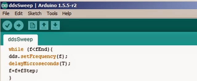
Then I turned my attention to writing the sweep generator code...

I set up two constants, fStart and fEnd, representing the beginning and end of the sweep. Then I simply stepped up a frequency variable, f, in equal increments, fStep, starting from fStart, until I reached fEnd. At each step, I waited T microseconds (plus the extra 950 or so microseconds the system forced me to wait).

Oh yes - I was also making it easy on myself by using my own DDS library's setFrequency() command.

That’s all there was to it...


I added a trigger pulse at the beginning to let my ‘scope know when to start. And a gate pulse to let me know when the measurement was valid (etc).  I could (and did) add any number of other refinements and diagnostic extras – but the bare bones are as described above.

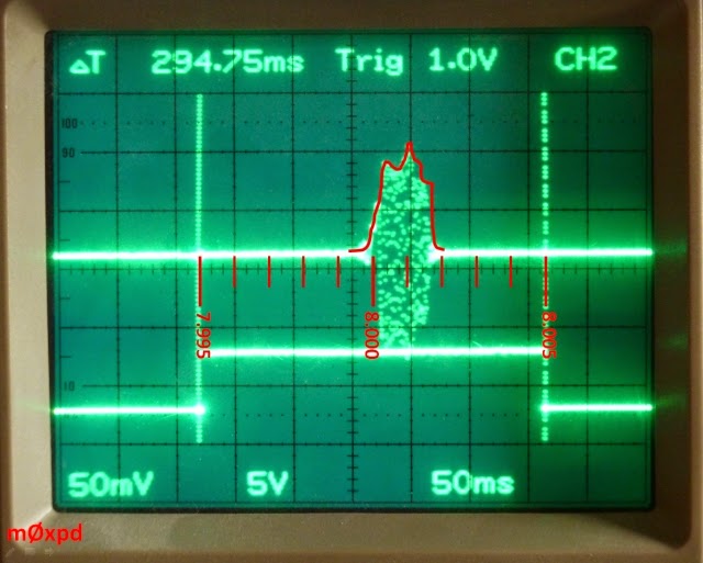
The results are seen below...


What is seen above is the frequency axis horizontally and the magnitude response vertically. It is a photograph of the screen of my digital storage scope on a “single shot” trigger. I have manually set the vertical cursors to correspond to the limits of the gate pulse, corresponding to the start and End frequencies (which, in this case, were 7.995 and 8.005 MHz). 

This might be easier to understand with a little annotation...


Here, I’ve added a frequency scale (just by interpolating between the start and end points) and I’ve drawn in a (linear) magnitude frequency response curve – by joining the dots! You can see that the passband is confirmed to lie between 8 and 8.002 MHz - just as I had established earlier by "conventional" testing.

Being a good boy, I had the filter loaded by a 50 Ohm terminator at the ‘scope input – if you remove that, you get the expected huge increase in voltage levels – but notice how the shape of the filter changes significantly...


It is important that we make measurements of our filters in realistic loading conditions if we want to avoid deluding ourselves!

You saw in my LTSpice model (above) that I used a 50 Ohm source and load resistor with the filter. I made a MATLAB model of the filter (using my own Two Port methods) and looked at the input impedance, which I found closer to 200 Ohms. Sure enough, the response of the "ideal" filter is "cleaner" if it is operated in a 200 Ohm environment - but I didn't get round to that level of detail yet. 

Now I have a viable RF Sweep Generator - let's see what we can do with it.

...-.- de m0xpd 


Friday 25 April 2014

Short Stay

Just back from an Easter holiday in Pickering...


with its special delights for the preserved railway enthusiast and angler. As before, we stayed at High Mill


but this time my three daughters and their partners were with us - so we had the excuse we needed to stay in the big house. Readers of this blog will remember that High Mill actually forms part of the boundary of the North York Moors Railway.

As usual, after satisfying the XYL's appetite to watch seabirds at the RSPB reserve at Bempton Cliffs, there were flocks of locomotives to be seen and, indeed, heard (the pretty Kitson built 0-6-2T loco that started its working life at Lambton colliery and wears number 29 has a lovely, mellow whistle). 

Having reveled in the grandeur of Sir Nigel Gresley last visit, it was nice to see the little Fowler 3F "Jinty" this time...


There was also a brace of Black Fives marching around - 44871 is seen seen here bringing "The Moors Explorer" into Pickering, taken from the garden of High Mill...


Later in the week, the same loco was to haul "The Yorkshire Coast Express" with me on board all the way to Whitby. It does run in Yorkshire. It does go to the Coast. I didn't notice anything particularly "Express" about it, though!

I took this little video of High Mill from the first carriage behind 44871 as we pulled out of Pickering - you can see what a great place it is, with its long garden and rooms offering outstanding views of the railway...


After pulling past the trout lake and the (now defunct) trout farm, the train soon reaches New Bridge, were the driver swaps single line working tokens with the signal man who comes down from his box to make this exchange. The levers at the New Bridge Signal Box control all the action at the Pickering end of the line...


Talking of signals (how about THAT for a link!) I took no radio gear this time, remembering the QRM I experienced during my last visit. 

High Mill owner, Mike, who had explained how both he and his wife Cheryl had enjoyed careers as Radio Ops, remembered my radio interests and dug out some photos of operator desks at GKA and GKZ, which I copied. Some parts of these copies are reproduced in the montage below...


The colour image (top left) shows Portishead, GKA, on the day of its closure (30/04/00). Mike visited on that day in his rather colourful cycling gear - so I've cropped the image to respect his privacy!

Much of my "train spotting" in Pickering is conducted from the viewpoint of the previously mentioned trout lake - where I spend a couple of hours every morning before breakfast and every early evening. This Easter I landed a total of 233 trout - the best ran to something around 5 pounds - nowhere near as big as the leviathans I have captured on previous visits, but great fun none the less and a great total given the time of year.

Another great time in Pickering - thanks to Paula at the trout lake, thanks to the NYMR and thanks to the hospitality of Mike and Cheryl Potter of the wonderful High Mill, Pickering.

All too Short a Stay!

...-.- de m0xpd

Sunday 6 April 2014

Arduino and the Si570

I've been wanting to experiment with replacing my little AD9850 DDS modules with the Si570 device. Not out of any sense of dissatisfaction with the former - more out of a spirit of adventure and in preparation for future experiments with extended bandwidth. The big problem with the Si570 - apart from cost - is the package.

I decided to solve the problem by mounting the awkward package on one of my little plug in modules, which start with a small printed circuit board...

Here are a few of the "carrier" PCBs, knocked up yesterday in my "back yard fab", along with an Si570


I got out my little USB microscope and did the best I could with my soldering iron, failing eyesight and shaking hands- here's a close-up shot from the microscope part-way through assembly...


Once the chip was on the carrier, I added some header pins to serve as "legs" for the module, which acts as an 8 pin DIL "wide" (i.e. 0.6 inch) package, which is infinitely easier for me to handle (and, indeed, see) than the original bare device...


Now - I just need to program the thing.

I have driven an Si570 before from a PIC (in my original multi-mode beacon) - that was a pretty brute-force piece of coding. This time I wanted something a little more elegant, so I looked around on the 'net.

The first fruit of that search was the ArduinoSi570 Library , by Gabriel Fournier.

I downloaded that library, but could not get it to compile, either with the provided example sketch or with my own simplified examples. Gabriel quickly and graciously answered an email asking for help - but his suggestion was that I should find another library! So I searched some more...

Fortunately, that search soon reminded me of Farhan's new Minima transceiver, and I found the "Radiono" code for it, which includes library resources for controlling the Si570. I downloaded that library and soon had modified the code (which is intended for the ATmega328P) to run on an Arduino MEGA, which allowed me to confirm that my new Si570 module was working correctly...


My real interest was in getting the new Si570 module running under the control of the Arduino DUE and - I'm ashamed to say - I still haven't succeeded in that goal.

My modified program now compiles and I can see the I2C activity between the DUE and the Si570, but they are not yet successfully communicating.

You can see how much I'm struggling by the presence of an empty coffee cup in the frame below - things are obviously bad...


I guess it won't be long before we have Si570-derived RF for the Arduino SDR - but not today!

...-.- de m0xpd