Sunday 18 October 2015

Powermaster Rectifier Replacement

After last week's RSGB Convention I called in at my Father-in-Law's, to be rewarded by a brace of vintage train controllers...


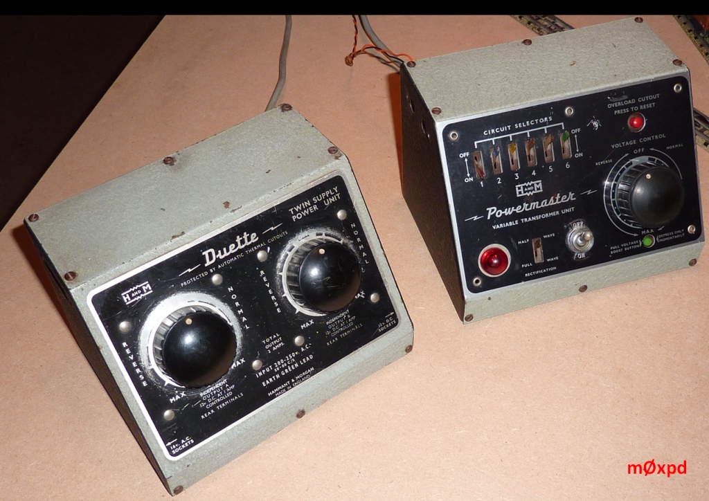
These devices, made by Hammant and Morgan Ltd, formerly of Watford, are the boat-anchors of the UK train controller world. They are old and heavy and made-to-last, unlike modern equivalents (in at least the first two attributes).

Fortunately I have a quiet obsession for collecting and operating old, heavy toy trains which have demonstrated their ability to last for over half a century...


so these controllers were ideal for my applications.

Of the two newcomers, the Duette offers two "channels" of control, whereas the Powermaster offers only one controllable output (plus some sector switching gear). It might appear that the Duette wins hands-down. However, the Powermaster is an entirely superior device, offering a genuine variable output voltage (rather than a single output voltage with a variable source impedance). This is achieved by a transformer with exposed secondary, over which a wiper can pass to tap off a desired voltage - rather like the way an antenna tuner with a "rollercoaster" inductor works. The result is something like a Variac (but not, in this case, an autotransformer).

There's a (flawed, but useful) description here, along with some interior photos of a newer generation of Powermaster, showing the variable transformer. Having linked to that site, it is important to repeat - the Powermaster is NOT an autotransformer. There is isolation between the mains voltages on the primary side and the SEPARATE secondary.

On test, the Duette still worked as intended. However, the Powermaster worked on its "reverse" output range, but not on its "forward" voltages, producing an output voltage reading on a meter, which quickly collapsed to zero under load (a 50 Ohm dummy load). Obviously it was not doing its job of working as a voltage source having low source impedance.

In light of the asymmetry described above, I suspected a fault in the old Selenium rectifier or the polarity change-over switching and associated wiring. Unfortunately, I could find no detailed descriptions of the Powermaster on the internet, so these notes describing my repair may be of interest to others caught in the same boat...

I removed the rectifier and figured out what the connections did (by visual inspection)...


To check my diagnosis, I lashed-up a temporary replacement outside the case - all the wires were sufficiently long to pass through the many holes conveniently available in the back of the case...


Having confirmed that this was all working fine, I made a (slightly) more permanent solution on a scrap of copper-clad board, with some pads formed by whittling away Cu in judicious places and a sprinkling of diodes (I had 1 Amp 1N4003s to hand and have used those for the moment)...


The holes in the PCB are arranged such that I can just screw this new home-brewed rectifier in place of the old selenium unit.

The wiring is self-evident - the only possible confusion being in connecting the Half/Full-wave rectification switch identified here on the front panel by a dashed red circle...


The switch is connected as follows...


The result? A perfectly-operating Powermaster, giving my 50-year-plus old toy trains slow speed performance which they never had before - all from a "period" controller.

Anybody seeking to make such a repair in their own vintage controller should attempt it only if they are appropriately qualified and then only at their own risk. I don't need your burnt-out armatures, house fires or electrocution on my conscience.

These controllers have another nostalgic significance for me - back in my childhood, they were the most convenient power supply to hand. A perfect place to start with some electronics experiments. Guess where the young m0xpd used to get his LT from!

In fact - I'm pretty sure the Duette IS one of my childhood controllers, inherited from my cousins, passed on to Father-in-Law - and now passed back with interest in the form of the Powermaster.

Now - time to play with some of that new slow-speed performance. Thanks Malcolm!

...-.- de m0xpd

Monday 12 October 2015

RSGB Convention

Just back from the RSGB Convention...


where I managed to avoid having too much over-ripe fruit and vegetables thrown at me by hecklers in my lecture, just before lunch on Saturday...


In fact, rather than hecklers, I was honoured by an enthusiastic and engaged audience, who listened to me rambling on about Arduinos and DDS modules very attentively.

The Buildathon on Saturday afternoon saw builders tackle the new Acorn II, which provides the hardware front-end of an SDR Receiver for HF. This was the first ever Buildathon at an RSGB Convention and was, in consequence, something of an experiment.

Those who signed up for the Buildathon tackled it with great enthusiasm and competence...


inspired and assisted by Steve, g0fuw, Dan, m0tgn and Lewis, g4ytn, who were the all-important mentors (without whom Buildathons don't exist) and Dennis, g6ybc, from Kanga, who was there to make sure the kit "delivered".

As well as those actually building, many people popped their heads round the door, looking at what was going on, during the course of the build.

The first receiver to be completed worked first-time...


In contrast, when I went to demonstrate my VFO to the builder of this new Acorn II, my VFO completely failed.

On return home, I re-loaded the code into the VFO system's Arduino UNO and it now works FB again (with no other changes / fixes required)...


This is interesting - it is the first time in my two and three-quarter year history of playing with Arduinos that I have ever experienced such a firmware "corruption" issue.

The Buildathon was declared a great success.

Indeed, the whole event was a pleasure to be part of, presenting as it did an opportunity to catch up with some familiar faces, to meet some new ones and to chat about matters of mutual interest. Better than the average Saturday afternoon!

...-.- de m0xpd

Saturday 3 October 2015

The URMSTON Regen Receiver

Now that the cat has been let out of the bag on the Kanga website, I guess it is OK to tell you - the second of the two receivers I was playing with a few weeks back is now revealed to be a collaboration with George, g3rjv, and friends at the G-QRP club...


As you see above, the receiver looks pretty in her first production build (even though I say so myself).

The new receiver has been developed particularly for the Buildathon at this year's Rishworth mini-convention, so the PCB layout has been made with special attention to the needs of first-time builders. There's lots of space between the components and plenty of elbow room for the soldering iron - no surface mount technologies here!

Also, I wanted participants at the Buildathon to be able to put together a practical receiver with controls on a real front panel. I  like the form-factor of some of Tim Walford, g3pcj's kits - but didn't think that a fixed front panel would be the best option for a raw tyro in a Buildathon, where time is tight and quick access for trouble-shooting might be invaluable. So I came up with a design that could be made in two parts and quickly plugged together - or pulled apart.

The result is seen here from behind...


The system relies on simple latching connectors for the controls (the female headers are supplied with lengths of cable ready-connected in the kit, so the builder only has to trim to length and solder to the controls) and brackets to fix the main PCB to the front panel PCB. But what could I use for the brackets?

Well - modesty almost forbids me from telling you,

After looking around the workshop for a while and scratching my head, I settled on the idea of using these abominations...


They are - I believe - called "modesty blocks" and they stand in place of carpentry skills in this era of particle board furniture.

They are available in a bag of a hundred for the price of a pint of fancy beer in a city-centre drinking establishment - which is to say they cost a few pence each, retail. They are made of a hard plastic and have two holes on 18mm centres in one plane and a single hole, midway between the other two, normal to them.

They make perfect brackets for the two PCBs of the little regen...


Here's a rather immodest view of the assembled unit...


In times of trouble, unscrewing two screws and pulling off five header connectors will separate the two sub-assemblies. But when fixed together, the blocks make the front panel perfectly rigid.

The front-panel ground-plane is connected to the rest of the receiver via one of the leads - without which the notorious hand-capacitance allows the unit to revert again to its secondary role as a Theremin!

The receiver is great fun to operate - pulling in AM, CW and (if you are patient and skillful) SSB signals on a piece of wet string. It is very sensitive. It is also VERY unlike the other types of receiver we are more used to playing with today. Fortunately I had developed some experience with regens from playing with my Paraset, but for regen virgins, this could be a surprise.

It has been a joy to be working directly with one of George's designs, on an "official" commission from George and Graham at the G-QRP club.

As a further joy (or embarrassment), Dennis at Kanga has named the kit The "URMSTON" - which is the postal town near which I live. Presumably the word is stuck in his mind after mailing so many things to me.

The kit is going to be launched at the G-QRP Buildathon on Friday 23rd October and will be available for general sale at the mini-convention on Saturday 24th and thereafter from Kanga.

I am pleased that my two receivers will be "cannon fodder" at the two big forthcoming Buildathons at UK Radio events this month - I only hope the participants will be pleased too!

...-.- de m0xpd