Monday 25 July 2016

OLED Display on the ESP8266 Beacon

My good friend and benefactor, g6ybc, just sent me a couple of little OLED displays to play with...


Since it is sitting here buzzing away on the bench, what better 'test bed' for the new display than the ESP8266 / AD9834 beacon, recently described?

I downloaded the Adafruit SSD1036 Library and I already had the GFX Library (and using the latter with the ESP8266 is a lot less of a headache than with the UNO, as memory isn't about to run out any time soon).

I soon had the little display plumbed into the proto-beacon (it only needs power and a couple of interface lines)...


and we were displaying useful status information (which previously had required a link to the PC and a Serial Monitor window)...


I did find one useful little wrinkle...

You need to define a 'reset line' for the display - even though you're not going to use one. Rather than waste one of the few precious GPIOs of the ESP8266, I tried defining one which doesn't physically exist.

It worked - program compiles and runs FB. Here I'm using GPIO 20 which (as ESP8266 users will know) isn't there - on the outside, at least!


If everything goes pear-shaped in a few days, I'll tell you.

I can even relate the pictures of my display with the results of other peoples' efforts in receiving my transmissions...


This is a cute little display, super-easy to link to the ESP8266 (or an Arduino) with only two lines. Plus, it makes a genuinely useful addition to the beacon.

...-.- de m0xpd


Sunday 24 July 2016

AD9834 / ESP8266 Beacon

Well - the connected ESP 8266 beacon is now running with its new AD9834 heart pumping pure RF sinewaves...


Last week's report was made in good faith - but I hadn't realized at time of posting that the DDS was only being controlled to VERY poor frequency resolution. In fact, I could only adjust the frequency in something like 3kHz increments. Obviously, something was very wrong!

I wasted a lot of brain cycles trying to track down the problem and ended up abandoning the AD983X library (which I could not get to work properly with either an Arduino UNO or Mega - much less the ESP8266).

Instead, I took inspiration from Diz Gentzow, w8diz's work (well reported by Bruce Hall, w8bh) and Akio Mizuno's Arduino AD9834 DDS and I went back to my old "Soft SPI" approach.

This paid dividends - after doing the initial development work with an Arduino UNO and a logic analyser, both of which you can see in the photo below, which shows the proto-beacon on the bench...


You can also see the amplifier I'm using for the beacon (it is the original prototype of the m0xpd / Kanga Sudden Tx shield) and the filter on the amplifier output.

As well as (correctly) controlling the AD9834, the ESP8266 connects to the internet to get the time from an NTP server, as has been described previously. This allowed the beacon to be heard immediately on its very first 'shout', with no intervention whatsoever from me.

Here are the reports from wsprnet.org of that first shout this morning...

and the same in visual format...


As well as transmitting WSPR, the beacon is transmitting other QRSS modes which could be received on "grabbers", such as that operated by Steen, la5goa in Norway...


(my callsign, 'm0xpd', seen twice in the red box).

I left the beacon running for a few hours and now there's a fuller 'net' of signal reports for the new beacon - here's the complete set of (WSPR) Rx reports since turn-on...


The next step is to turn the pile of spaghetti on the bench into something a little more permanent.

...-.- de m0xpd


Sunday 17 July 2016

AD9834 and the IoT Beacon

I've been playing with a new RF generator for the IoT beacon...


Actually, I do myself a disservice, because I've done rather more than just play with the RF generator.

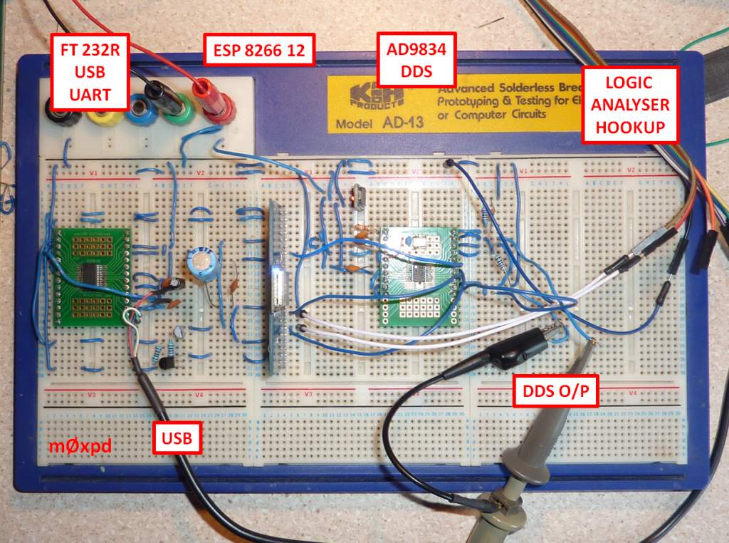
First, I've replaced the little USB to serial dongle which I used to program the original system and built a complete interface, using the same FTDI chip which was on the original dongle. The thinking behind this is to avoid the requirements for a clumsy interface to some of the more unusual UART lines (such as RTS and DTR), which are not taken out to the nice big header pins on a standard USB-Serial device.

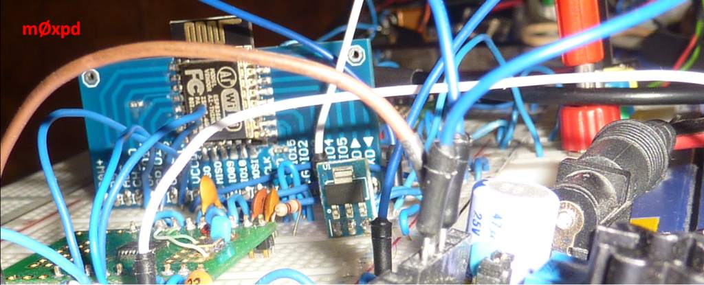
Then, I've changed the RF generator - moving from the AD9850 DDS module as used previously to the AD9834 chip. You can see the hardware here...


Getting the FT 232R device talking to the ESP8266 was easy. But arranging the interface to the AD9834 was a little less straightforward.

I have the AD9834 on a DIL carrier (thanks Dennis) and I built the master clock oscillator on some "prototyping area" at the top of that carrier board, as you can see in the photo below...


The hardware all seemed to work FB - so all that was needed was some code for the ESP8266.

Fortunately, Nick Johnson has written an Arduino library to control the AD983x, which is available here .

Unfortunately, the library didn't work with the ESP8266 (I can't say whether it works with anything else as I didn't try it).

I did some head scratching and ended up writing some code which implemented a software SPI interface between the ESP8266 and the AD9834 and got that running OK.  That was enough to allow me to see that the problem with the library appeared to be an issue with the specification of the SPI Mode...

I played with a little test program for SPI on the ESP8266...


Setting the SPI DataMode to 2 (which was the mode used in the library) results in a data transfer in which the data is read at upward transitions of the clock signal, as demonstrated by this capture of the output of one burst from the test program above on the logic analyser...


(I've added the red annotation to the logic analyser screen to try to show what's going on - the arrows define the time instants when the data is valid and the binary data speaks for itself).

If the DataMode is changed to 1, the data is valid on the falling transitions of the clock ...


Certainly, the AD9834 data sheet specifies that the serial data should be valid on downward transitions of SCLK (see Figure 5, page 6).

Suddenly, the AD9834 was working fine, producing nice sine waves at its output...


What you can't see from the clumsy photo of my 'scope screen above is that the frequency is actually being changed once a second - the ESP8266 can control the AD9834.

A note of caution: there are some known 'holes' in the ESP8266's implementation of the SPI Modes (mainly with the clock 'polarity' - not with clock phase). I don't know if what I've described above relates to ALL applications of the ad983x library - or just to its use with the ESP8266. I haven't the time (or the need) to test with other controllers. If you use it elsewhere, take care.

All that I care about is that the FT 232R / ESP8266 / AD9834 combo is now ready to work as the 'brain' of a QRSS beacon.

...-.- de m0xpd


Wednesday 13 July 2016

getting there on Kindle

Those of you with an ecological objection to Treeware, those of you who baulk at the price of a physical object or its delivery, and all tablet-toting neophiles might be interested to hear that my little book is now available on the Kindle platform...


You can find the new electronic edition on the same amazon.com, amazon.co.uk, etc pages as before.

Perfect summer holiday reading!

...-.- de m0xpd