Fortunately, Eamon “Ed” Skelton, ei9gq, had just published a simple design using a PIC microcontroller in RadCom (Vol 84, No 12), so I was laughing. The same design is featured on Ed’s own pages. All I had to do was make a few mods (I wanted, for example, to be able to interface both a paddle and a straight key to the same device) and I was ready to go.
My schematic is shown below…

Fortunately, I know PICs pretty well and had the ability to modify Ed’s code and burn it into a chip (using my PICStart programmer).
The keyer works just fine (thanks Ed) and I boxed it up with an internal piezo sounder to use with rigs without sidetone and a switching relay to key valve rigs for which the open collector transistor wasn’t going to work. That little piezo sounder got me thinking…
We all spend a lot of time worrying about the spectral purity of our RF emissions and thinking about the way in which we key the output stage of our CW rigs. A sudden switch-on of a pure tone generates other frequency components. That is just as true at audio frequency as it is at RF. So – when we switch a sidetone generator, we really ought to apply a carefully designed envelope to the signal, rather than just switch it on and off. This same method is used in audiometers used to test hearing – pure tones are presented to the patient at different levels and they are gated by an exponential envelope, rather than crudely switched on and off, in order that hearing is tested strictly one frequency at a time!
A little search on the ‘net soon tracked down a sidetone generator circuit by G Forrest Cook, wb0rio, which is presented as a “Smooth Tone Clickless CW Sidetone Generator” – exactly what I wanted! You can find the original here .
The circuit works by making a pretty pure sinusoidal tone (produced by filtering a triangular wave) which is then passed through a voltage-controlled amplifier. Rather than crudely switching the waveform “on” and “off”, the VCA scales the tone with a nice exponential “attack” and “release”. I made a Spice simulation of the relevant part of the circuit to understand how it operates – you can see the result below.

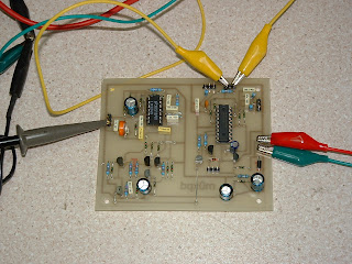
Now I couldn’t resist building a keyer with “proper” integral sidetone oscillator and so I pulled together a PCB in Eagle – you can see my prototype below.

I now use the keyer / sidetone combination in all my H/B rigs. It is built into my “Funster PLUS” (post to follow) and it is particularly useful in keying my SDR rig – as there is an 80msec delay between pressing the key and hearing the sidetone on my SDR set-up otherwise. 80msec might not sound much to you – but it is enough to mess up even my lousy CW!
…-.- de m0xpd

Thanks for sharing, M0XPD. I have been playing around with ei9gq's design too. I made a couple of K3NG's arduino based keyer system ( http://blog.radioartisan.com/arduino-cw-keyer/ ) which is packed full of features but for my micromountaineer I think I'm going to use EI9GQ's design. Perhaps I missed it but did you happen to post your final schematic of the PIC keyer with the sidetone? If not, I would love to see it but you've provided enough info to get the idea without seeing the schema. I enjoy your thoughts on using a quality sidetone. Trying different sidetone circuits with a keyer design is part of the fun. Thanks for all your contributions. 73
ReplyDelete