Sunday, 24 February 2013

Arduino Beacon

Here's the story of my new multi-mode QRP radio beacon built around the Arduino - or, more properly, around my homebrew clone, the WotduinoTM.

I ended the post on my Arduino DDS shield with the words "perhaps I'll use the wait to start writing some Wotduino beacon code". Well, despite more than the usual volume of traffic of distractions keeping me away from leisure activities over the past few weeks, I've managed to steal some moments to keep me (nearly) sane...

 
The beacon started with the usual lash-up on the bench, hooking the previously reported Wotduino and DDS Shield up to a driver and a transmitter module, as previously used for the Raspberry Pi beacon...


You can see that - in addition to the usual culprits - there is also some evidence of a receiver, a key interface and a tuning control in the picture above (so you can guess what will be appearing in future posts).

The experimental beacon was soon pumping out its tidings of great joy and getting rewarded by acknowledgements on QRSS Grabbers, such as this very first spot, seen at PA9QV...


(I've added the red text annotation to help those new to viewing these images - first to decode the Morse Code in my FSK-CW signal and then to emphasize the italicized text version of my "Hellschreiber" call).

Simultaneously (or, at least, at different points in its 10 minute operating cycle) the Arduino Beacon produces WSPR messages and these were decoded and reported automatically by reporting stations all over the place. Here, for example, is a map showing good performance to the US on 11 and 12 February...

 
In the spirit of work that elevated the humble eBay DDS module to a fancy Arduino "Shield", I wanted to formalize the Arduino Beacon and so I have produced a "Transmitter Shield", which takes my QRP Tx Module (with its "Ugly weekender" heritage) and places it in the familiar "Shield" format...


This new shield includes a driver stage to amplify and distribute the DDS signal, a power stage (mainly used to provide 5V for the rest of the system from the "12V" supply used for the Transmitter), a Keying Stage which allows the Arduino to turn the transmitter on and off to without switching transients (which radio folk call "keying" - from the action of the telegraph key) and the RF power stage itself.

The power stage is simply two 2n3904 transistors which are driven to produce 500mW. This involves dissipating a fair amount of energy in the little transistors - so I treated them to a homebrew heatsink, hewn out of a scrap of Aluminium (apologies to our North American readers for the spelling lesson)...


The similar power stage in my "Funster Plus" rig doesn't have a heatsink - but the beacon spends a lot more of its duty cycle transmitting, so I felt it had earned the luxury of more effective heat management!

The Transmitter Shield sits on top of the existing layers to make a nice "Beacon Sandwich" (pun intended)...


To celebrate the new hardware, I took the liberty (and bandwidth) to send a more lavish (or, at least, more verbose) sequential multi-tone "Hellschreiber" proclamation, here seen at g3vyz


The beacon is still multi-mode; in addition to the modes seen above it also sends "m0xpd/arduino" in (QRQ) Morse and participates in the WSPR mode, as seen here achieving my best-ever westward QRP beacon dx to nj6d in Arizona...


As the Arduino does not provide such a rich programming environment as the Raspberry Pi, there were a couple of points at which my attempts to get m0xpd beacon operations running on the new Arduino platform threw up some issues...

Firstly, readers may remember my delight on discovering "Associative Arrays" - or "Dictionaries" as they are called in Raspberry Python land. I used these to look up the Morse code equivalent of a character in my messages back on the RPi beacon.

Arduino does not offer native associative arrays. You can, of course, use C libraries to pull in this functionality, but I decided to take a different tack...

My code on the Arduino looks for the ASCII value of each character in a Morse message, then uses this ASCII value to point to the appropriate element of a "char" array of strings of 0s and 1s, which represent the Morse equivalent of the character (0 for a dit, 1 for a dah). I started the array at the ASCII value (decimal) 40, as there's no character send-able in Morse before that.

The process is shown here in my routine to send FSK-CW (the straight CW routine uses the same resources)...


As an example, the comma has ASCII value 44, so its the fifth element in my array (Arduino arrays start from index 0)...


The second little wrinkle in the Arduino Beacon code was unexpected. The RPi has the luxury of an internet-derived clock, so timing for a beacon is supremely easy. By contrast, Arduino only has a counter which runs from the instant the program is started and from which time relative to that start instant can be computed. The counter is ultimately derived from the 16MHz crystal-controlled oscillator. 

Once I had my beacon up-and-running, I noticed that it was running slow - it would lose a few seconds every six hours, indicating that my 16MHz crystal was actually 15-and-a-bit MHz! I fixed it by telling the Arduino that there are only 59995 milliseconds in a minute and that - to the level of accuracy required - has done the trick. You can see the lie in the code excerpt below, which shows the (start of the) main timing loop of the beacon...


Now its time to try to find space - amidst all the distractions - to do some more work on the receiver side. 

...-.- de m0xpd

Saturday, 9 February 2013

Arduino DDS Shield

Following the fun-and-games I had with the little eBay AD9850 DDS module in Raspberry Pi land, I decided to follow Ron's inspiration even more literally than before and team up the module with an Arduino.

Or, at least, with my homebrewed "Wotduino".


Here's the schematic I developed in Eagle...


I represented the DDS module as a component in Eagle and was intending to upload the library to the CadSoft site for you to share, but CadSoft claim not to recognise my email address (despite the fact that there's another library of mine already there, proudly displaying said email address). Stuff it then - collaboration can wait 'til another day.

The module only took up a small fraction of the available area on the shield, so I added a couple of dual flip-flops to generate a quadrature squarewave output for future games with Tayloe detectors.

Here's my copper plan...

Here's the finished board, seen from above...


You can see where I had to gnaw away a little of the Module PCB (lower right) to fit with the DIL package - there wasn't quite so much space in real life as my Eagle board layout suggested!

This being my first ever experience of a Wotduino shield (much less an Arduino shield) I was interested to get some pukka "stackable headers" to allow the new shield to ride shotgun atop the Wotduino...


The board works a treat - the picture above is actually part of an impromptu 40m QRP CW rig I've lashed together today using the Wotduino. It works nicely - well enough to raise Terry, g4ayr, on the rig's first shout. But just as Terry and I started to talk, the band erupted with a crowd of speed freaks sending - . ... -, so I'll wait until things have calmed down before I strike up my genteel iddy umpty again.

Perhaps I'll use the wait to start writing some Wotduino beacon code.

 ...-.- de m0xpd
Sunday, 3 February 2013

KEYERduino

Now I've broken my duck with Arduino, it's time to look at some applications.


Having already got the "made a keyer" T-shirt for PIC and Raspberry Pi, the implementation of a Keyer seems to be turning into my "Hello World" example for microcontrollers, so off we go again with the "KEYERduino"...

Here's the program (what the illuminati call a "sketch" in Arduino-speak):

It is all simple enough - three input "buttons" being read and generating a digital output - just an extension of the button tutorial on the Arduino website.

In the present case, not only does the LED associated with pin 13 light up - we're also thinking of the same digital output driving the base of an open-collector transistor to key the transmitter. Also, only the straight key input works precisely like the button tutorial, simply "lighting the LED" when pressed. Closing any of the other two "buttons" triggers generation of the "dits" and "dahs" of Morse code, making an "iambic keyer". Oh yes - I nearly forgot - I also included a nasty, square-wave sidetone generator.

Here's the circuit, expressed in the unique format of Fritzing, much beloved of the Arduino community...


Fritzing isn't really my cup of tea - its OK for generating the sort of easily-accessible images above but it seems very much harder to make proper schematics with Fritzing than with a tool like Eagle.

Of course, nobody in their right mind would permanently implement a Keyer on an Arduino - it simply isn't worth burning the value (~£14) of the Arduino in something as trivial as a keyer. But there are some cases where it might just be excusable:
  • As a learning exercise - beyond the button tutorial
  • When part of a more complex application - such as a MEPT beacon
  • When you are just using the bare chip in a home-brewed board - cheap as chips!
Anyway - here's my keyer, running on the cheaper-than-chips WOTDUINO...


Not only is my implementation reasonably cheap (~£4). Not only was it an interesting learning exercise. But also, it might be the start of a more complex ham radio application of the WOTDUINO. Watch this space!

 ...-.- de m0xpd

What do I know?

Here's the story of a notorious late adopter's first foray into the world of Arduino.


As a long-term PIC advocate, I've been generally disinterested in matters Atmel and particularly put off by the statement that Arduino is intended for a bunch of wierdos (sorry - that should read "is intended for artists, designers, hobbyists, and anyone interested in creating interactive objects or environments"). However, things have changed...

I guess it started when I looked at Ron, NR8O's use of an Arduino to drive the eBay AD9850 DDS module. The Arduino looked pretty neat in that application - and you program it in a real programming language! Then I read Limor Fried's comparison between Microchip and AVR microcontrollers. Interesting. Given the enjoyment I'd had with my new Raspberry Pi (Blogs Passim), I thought perhaps it was time for me to join hands with all those liberals who have sewn Arduinos into their gaily coloured clothing.

Of course, that wasn't going to see me exchange my shekels with an authorised Arduino shop - particularly as I'd noticed that you can buy a kit of components for an Arduino clone for pennies on eBay. I got me a kit and started to think about how I could put it together on something more permanent than a solder-less breadboard.

Credit where credit's due - Arduino does publish a homebrew design for cheapskates like me on the Arduino pages but that didn't float my boat. So, after some searching around, I found Johan von Konow's design for a DIY Arduino - the Nanino.

Johan publishes a copper pattern for the Nanino, but I wanted to have the flexibility to change things - so I brewed up my own design in Eagle.

Update (28/09/2013): these Eagle files are now available for free download - see the link in my comment below.

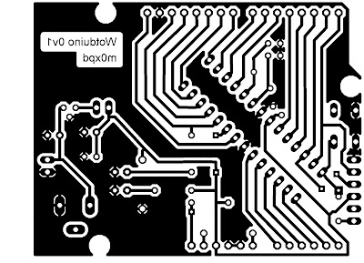
Here's my (current) copper pattern (seen from the component side)...


and here's the first board...


You can see the Nanino's influence in positioning the chip at a jaunty 45 degree angle!

I used Limor's (/LadyAda's) excellent Arduino resources within her extensive Eagle Library to simplify the design of the board, with its standardized profile and connector positions. 

The board is programmed via a USB to serial adapter which implements a Virtual COM Port. You need to connect to the DTR ("Data Terminal Ready") pin on the adapter to access the "auto reset" functionality in uploading "sketches" to the board - otherwise you're into all sorts of nonsense about manually pressing the reset button. Don't be fooled by the RTS pin - this means "Ready to Send" in the language of UARTs and isn't a misprinted abbreviation of Reset.

You can see the adapter (and the connection to the DTR pin) here...


If you are wise enough buy your Arduino kit from 4Tronix, the USB adapter arrives already modified so as to bring the DTR line to the header plug that connects directly to my board's serial programming port, saving you from the messy hook-up in the photo above. Beauty!

I call my new board WOTDUINO (pronounced "What do I know"), making it particularly suitable for people with little confidence and low self-esteem. It is also possible to build a similar version (pronounced "What do WE know"), which is suitable for groups of people who don't think they measure up HI HI.

Now let's see what it can do.

 ...-.- de m0xpd