After the fun-and-games with Morse and the Raspberry Pi yesterday, I decided to turn my hand to something a little more subtle - something which couldn't have been done more easily on a PIC!
Following on from the inspiration provided by Michael at MitchTech, who described a Physical Email Notifier using the RPi, latterly picked up by the good folks at Adafruit, I mixed in some Morse ...
My code uses Michael's technique to parse an Atom feed from a Gmail account every minute and then announces the name of the senders of all unread mails by Morse Code on GPIO 11 of the RPi.
You saw earlier how this can flash an LED or key a transmitter. You could use the same open-collector interface to switch a buzzer / sounder to let you hear the Morse.
The code uses a neat feature of Python (and other languages too, for all I know) to make the mapping between alphanumeric characters and their Morse representation: "Dictionaries". These were a new discovery for me yesterday - makes learning new programming languages actually worthwhile!
I generate a string of 0's and 1's for each Morse character; 0 for a dit and 1 for a dah. The rest is pretty self-explanatory.
You'll need to edit the code to insert your username and password - I don't want you reading my emails!
The code tries to announce only the first name of the sender (by searching for the first space in the "author" field). If there isn't such a space, it will just encode the entire author string as Morse - even including the new "ac" bigraph for "@".
As well as trying to get "GISTS" running on this post, I also uploaded both the Gmail Notifier and the iambic keyer Python code to a site for your easy downloading convenience...
The Gmail notifier is available here
The iambic keyer is available here
Enjoy!
...-.- de m0xpd
Sunday 30 December 2012
Saturday 29 December 2012
Keyer on RPi
This Christmas, along with other fine gifts, Santa gave me a Raspberry Pi.
In this brief lull in hostilities between Christmas and New year I've stolen a couple of hours to play with my new toy. I have to say I'm impressed!
It has been a pretty steep learning curve, because I didn't really know much about the whole Linux universe when I started. I've used a MAC at work for the past couple of years - but MAC encourages such a superficial engagement with the computer that you don't need to know anything about the nuts and bolts!
I was greatly helped by another present from Santa - the Raspberry Pi User Guide by Upton and Halfacree. That has been a good little book, which gave me a useful kick start. However, I didn't want just to light an LED or detect a button push as my baptism on the GPIO - so I decided to make a keyer...
I approached the project with a little trepidation, because Eben says in the User's Guide referenced above ...
That bothered me, because it was exactly the availability of the GPIO interface that attracted me to the Pi in the first place, promising a convergence between real computing and the PIC-based fun-and-games I've been describing on these pages. I hoped that the "real-time" warning (repeated on the Project Home Page for the GPIO module I used) wasn't going to threaten that promised convergence. Yes - I know that a morse keyer isn't exactly pushing the boundaries of real-time operation - but I also know from experience that a surprisingly small latency (of only 80 milliseconds) in a keyer is enough to make operation difficult.
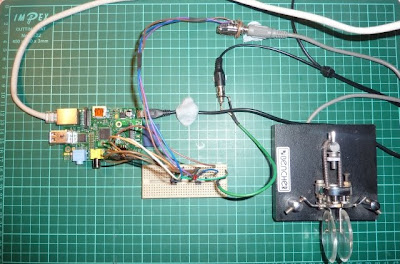
Here's the circuit I hooked up...
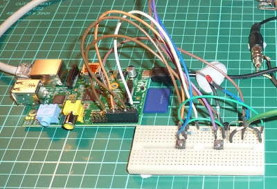
You can see that three GPIO lines are used for interface; one for each of the paddle's switches and one to key the transmitter (through the open collector). I started development with some little momentary action push-button switches which I left on the breadboard in parallel with the interface to the twin paddle, as you see in this picture...
Talking of interfacing to the RPi GPIO lines, I really like this solution - I shall have to buy one or make a copy!
Before we go on to describe the code, a warning. Remember that I started this knowing NOTHING about programming in Python, so what follows is an account of how something can be done, rather than how something should be done.
My code uses a Python module to access the GPIO port and I chose to use the module recommended in the User's Guide.
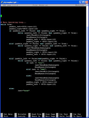
The code is seen in the windows below - I have been connecting to the Pi through SSH using the PuTTY SSH Client . The windows below show the Keyer program listed in the Nano editor. You don't have to work in this rather spartan way - I chose to do so in order to learn more about console/terminal interaction with Linux.
The first window shows some configuration stuff and some initial functions...
The second window shows the main operating "loop" of the code...
I don't know just how bad a piece of Python the above code is. All I know is that I learned a bunch from writing it and that the resulting keyer works perfectly. Having said that, it is utterly pointless as I already have my own Keyer solution and its more Rhythmically sophisticated derivative!
...-.- de m0xpd
Update:
Perhaps this wasn't just a Raspberry Pi learning exercise - it could be a tool for wireless telegraphy. To prove it (to myself, at least), I just used the keyer and my Funster Plus rig (which ironically already has a keyer built into it!) to have a quick QSO with Wally, operating the GB0YAM station on 40m at the Yorkshire Air Museum. Reminded me just how sloppy my CW has become!
Update 2 (September 2015)
Some kind reader just pointed out that there is a problem runing the code in the images above - I tried it and agree s/he is right. The code was working back in 2012, but isn't working today (that's to say I was doing something different back then).
In order to make the code work correctly, we need to make sure the variable "last" is defined before entering the main "while" loop of the program - here's a complete listing of the code, with the required addition...
#!/usr/local/bin/python
import RPi.GPIO as GPIO, time
# setup GPIO options...
GPIO.setmode(GPIO.BOARD)
GPIO.setwarnings(False)
# setup IO bits...
GPIO.setup(11, GPIO.OUT)
GPIO.setup(12, GPIO.IN)
GPIO.setup(16, GPIO.IN)
# check initial state...
GPIO.output(11, False)
def SendDit(DitLength):
""" Sends a Dit..."""
KeyLength=DitLength
KeyDown(KeyLength)
Last_Element="dit"
return Last_Element
def SendDah(DahLength):
""" Sends a Dah..."""
KeyDown(DahLength)
Last_Element="dah"
return Last_Element
def SendSpace(DitLength):
""" Wait for inter-element space..."""
time.sleep(DitLength)
return
def KeyDown(KeyLength):
""" Keys the TX """
# set the output to Key Down...
GPIO.output(11, True)
time.sleep(KeyLength)
# clear the output ...
GPIO.output(11, False)
return
DitLength=0.075
DahLength=3*DitLength
# here's the additional line (23/9/2015)...
last="none"
# Main Operating Loop...
while True:
paddle_left=GPIO.input(12)
paddle_right=GPIO.input(16)
if (paddle_left == False) and (paddle_right == True):
while (paddle_left == False) and (paddle_right == True):
last=SendDit(DitLength)
SendSpace(DitLength)
paddle_left = GPIO.input(12)
paddle_right = GPIO.input(16)
elif (paddle_right == False) and (paddle_left == True):
while (paddle_right == False) and (paddle_left == True):
last=SendDah(DahLength)
SendSpace(DitLength)
paddle_right = GPIO.input(16)
paddle_left = GPIO.input(12)
elif (paddle_left == False)and(paddle_right == False):
while (paddle_left == False) and (paddle_right == False):
if last == "dit":
last=SendDah(DahLength)
SendSpace(DitLength)
elif last == "dah":
last=SendDit(DitLength)
SendSpace(DitLength)
else:
last=SendDah(DahLength)
SendSpace(DitLength)
paddle_right = GPIO.input(16)
paddle_left = GPIO.input(12)
else:
last="none"
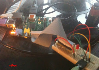
I have just tested the operation of the code and confirmed that it runs FB on my original Pi - here's the hardware I just lashed together for the verification (the battery isn't part of the system!)...
Thanks to our "Unknown" commenter (below) and apologies for any inconvenience to others - I still can't understand the origin of this issue, as the Keyer was working perfectly well before - well enough for me to use it in a QSO, as described!
In this brief lull in hostilities between Christmas and New year I've stolen a couple of hours to play with my new toy. I have to say I'm impressed!
It has been a pretty steep learning curve, because I didn't really know much about the whole Linux universe when I started. I've used a MAC at work for the past couple of years - but MAC encourages such a superficial engagement with the computer that you don't need to know anything about the nuts and bolts!
I was greatly helped by another present from Santa - the Raspberry Pi User Guide by Upton and Halfacree. That has been a good little book, which gave me a useful kick start. However, I didn't want just to light an LED or detect a button push as my baptism on the GPIO - so I decided to make a keyer...
I approached the project with a little trepidation, because Eben says in the User's Guide referenced above ...
"If true real-time operation is required for your project, the Pi may be a bad choice. Instead, consider using a microcontroller platform such as the popular open-source Arduino..."
That bothered me, because it was exactly the availability of the GPIO interface that attracted me to the Pi in the first place, promising a convergence between real computing and the PIC-based fun-and-games I've been describing on these pages. I hoped that the "real-time" warning (repeated on the Project Home Page for the GPIO module I used) wasn't going to threaten that promised convergence. Yes - I know that a morse keyer isn't exactly pushing the boundaries of real-time operation - but I also know from experience that a surprisingly small latency (of only 80 milliseconds) in a keyer is enough to make operation difficult.
Here's the circuit I hooked up...
You can see that three GPIO lines are used for interface; one for each of the paddle's switches and one to key the transmitter (through the open collector). I started development with some little momentary action push-button switches which I left on the breadboard in parallel with the interface to the twin paddle, as you see in this picture...
Talking of interfacing to the RPi GPIO lines, I really like this solution - I shall have to buy one or make a copy!
Before we go on to describe the code, a warning. Remember that I started this knowing NOTHING about programming in Python, so what follows is an account of how something can be done, rather than how something should be done.
My code uses a Python module to access the GPIO port and I chose to use the module recommended in the User's Guide.
The code is seen in the windows below - I have been connecting to the Pi through SSH using the PuTTY SSH Client . The windows below show the Keyer program listed in the Nano editor. You don't have to work in this rather spartan way - I chose to do so in order to learn more about console/terminal interaction with Linux.
The first window shows some configuration stuff and some initial functions...
The second window shows the main operating "loop" of the code...
I don't know just how bad a piece of Python the above code is. All I know is that I learned a bunch from writing it and that the resulting keyer works perfectly. Having said that, it is utterly pointless as I already have my own Keyer solution and its more Rhythmically sophisticated derivative!
...-.- de m0xpd
Update:
Perhaps this wasn't just a Raspberry Pi learning exercise - it could be a tool for wireless telegraphy. To prove it (to myself, at least), I just used the keyer and my Funster Plus rig (which ironically already has a keyer built into it!) to have a quick QSO with Wally, operating the GB0YAM station on 40m at the Yorkshire Air Museum. Reminded me just how sloppy my CW has become!
Update 2 (September 2015)
Some kind reader just pointed out that there is a problem runing the code in the images above - I tried it and agree s/he is right. The code was working back in 2012, but isn't working today (that's to say I was doing something different back then).
In order to make the code work correctly, we need to make sure the variable "last" is defined before entering the main "while" loop of the program - here's a complete listing of the code, with the required addition...
#!/usr/local/bin/python
import RPi.GPIO as GPIO, time
# setup GPIO options...
GPIO.setmode(GPIO.BOARD)
GPIO.setwarnings(False)
# setup IO bits...
GPIO.setup(11, GPIO.OUT)
GPIO.setup(12, GPIO.IN)
GPIO.setup(16, GPIO.IN)
# check initial state...
GPIO.output(11, False)
def SendDit(DitLength):
""" Sends a Dit..."""
KeyLength=DitLength
KeyDown(KeyLength)
Last_Element="dit"
return Last_Element
def SendDah(DahLength):
""" Sends a Dah..."""
KeyDown(DahLength)
Last_Element="dah"
return Last_Element
def SendSpace(DitLength):
""" Wait for inter-element space..."""
time.sleep(DitLength)
return
def KeyDown(KeyLength):
""" Keys the TX """
# set the output to Key Down...
GPIO.output(11, True)
time.sleep(KeyLength)
# clear the output ...
GPIO.output(11, False)
return
DitLength=0.075
DahLength=3*DitLength
# here's the additional line (23/9/2015)...
last="none"
# Main Operating Loop...
while True:
paddle_left=GPIO.input(12)
paddle_right=GPIO.input(16)
if (paddle_left == False) and (paddle_right == True):
while (paddle_left == False) and (paddle_right == True):
last=SendDit(DitLength)
SendSpace(DitLength)
paddle_left = GPIO.input(12)
paddle_right = GPIO.input(16)
elif (paddle_right == False) and (paddle_left == True):
while (paddle_right == False) and (paddle_left == True):
last=SendDah(DahLength)
SendSpace(DitLength)
paddle_right = GPIO.input(16)
paddle_left = GPIO.input(12)
elif (paddle_left == False)and(paddle_right == False):
while (paddle_left == False) and (paddle_right == False):
if last == "dit":
last=SendDah(DahLength)
SendSpace(DitLength)
elif last == "dah":
last=SendDit(DitLength)
SendSpace(DitLength)
else:
last=SendDah(DahLength)
SendSpace(DitLength)
paddle_right = GPIO.input(16)
paddle_left = GPIO.input(12)
else:
last="none"
Thanks to our "Unknown" commenter (below) and apologies for any inconvenience to others - I still can't understand the origin of this issue, as the Keyer was working perfectly well before - well enough for me to use it in a QSO, as described!
Monday 24 December 2012
Digital TS Rocks!
I ended my last post saying "time to get on and USE the new SOIC chip and the swanky new jumpers". I've been true to my word...
Here you can see a 1MOhm Analog Devices AD5242 digital potentiometer serving as the "Drive" control in my Digitally Controlled Tube Screamer.
Yes - I know the original had a 500k potentiometer in this position - but you can't buy 500k digital Pots for love or money, so I'm just using the first 128 positions of this 256 position 1M part. What's worse, this is a dual device, so I'm using less than a quarter of the resources I paid good money for :-(
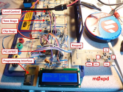
Zooming out, here's a view of the m0xpd experimental Digital Tube Screamer in its current incarnation...
As you see, I'm still using two single op-amps (NE5534s). This is for two reasons; firstly to spread the circuit out on the breadboard so as to make things more accessible and secondly (and much more importantly) to irritate all those aficionados who believe that the only op-amp to use in a Tube Screamer worthy of the name is a JRC4558.
The other digital potentiometers are Microchip MCP4131s - a 100k part for the level control and a 10k part for the tone control. Again, I know that the original Tube Screamer had a 20k part in the tone control but my analysis of the Tone Control Network convinces me that a 10k substitution won't make a blind bit of difference. These new digital pots are better to work with than the AD 5220 parts I used in the original Digital Tube Screamer, which had a clunky "increment/decrement" control interface. Now with the MCP4131s I can load up desired numerical settings explicitly.
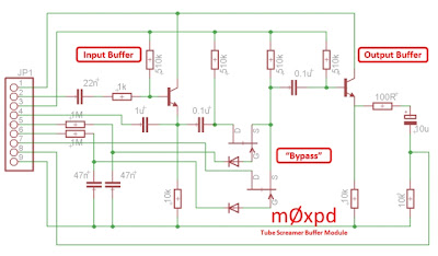
Also visible in the photo above (at the right-hand side) is a plug-in module built on Veroboard. It contains the input and output buffers and the Tube Screamer's electronic "Bypass" switching...
I know there are a lot of purists, flat-earth theorists and obsessives out there who like (what they judgementally call) "True" bypass switching. I admire the FET switching circuit and I might use it again in some other stompbox experimentation, which explains why I went to the trouble of knocking up the module.
If others want to follow suit, here's my schematic...
Now it is all running, I have the digital pots under control of the PIC, communicating through a common I2C bus (turned out I didn't need all the IO lines of the 16F887 after all).
I have all the variable parameters of the Tube Screamer - including the bypass switching - under the control of the PIC, via its keypad-based user interface.
Most excitingly of all, I have a range of PRESET configurations, which can be called up at the press of a button, allowing me to call on the full range of sounds the Tube Screamer can generate without fumbling with knobs! It is much better than having more than one Tube Screamer.
Now I need to decide on how I'll arrange some footswitch control.
...-.- de m0xpd
Friday 21 December 2012
Breadboarding Refinements
Those who have idled away their lives reading these ramblings on previous occasions will know that I'm a fan of "Solderless Breaboards". Here's a tale of two little refinements made recently to straighten the path of my breadboarding.
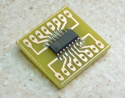
The next steps of my digital implementation of the "Tube Screamer" require some different digital potentiometers. One of these was available only in SOIC packaging - hardly the thing to plug into one of my beloved breadboards. Unfortunately, I am too cheap to consider exchanging my shekels for a commercial solution to this problem. Fortunately, making one is the work of only a few pleasurable moments...
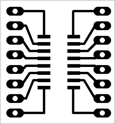
Here's a copper pattern if you want to make one of your own...
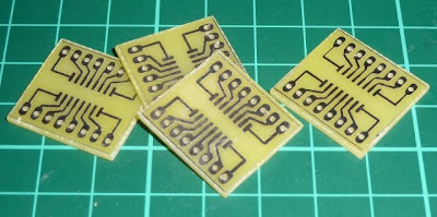
I etched a few onto a scrap of FR4...
and drilled and sawed them...
Now for the hard part - soldering one of these microscopic devices onto the new carrier...
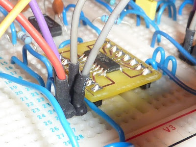
It went surprisingly well, given my poor eyesight. All that was then needed were some legs to fit into the breadboard...
Why - it is nearly as good as a chip in a DIL package!
Whilst we're on the general subject of breadboarding, I may as well tell you about my new jumper wires...
I had always admired those nice flexible jumper wires you can buy in little sets - but once again, my healthy reluctance to spend money on old rope (or little lengths of wire, in this case) has prevailed. Until recently...
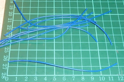
I cut up a few lengths of wire...
then I prep the ends...
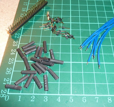
... and gather together the other ingredients for this simple recipe.
These are terminal "pins" made from pieces of chopped up header plug and little lengths of heatshrink...
I solder on one end, add two lengths of heatshrink, then solder on the other end.
A little judicious stretching with the ends of a small pair of needle nosed pliers helps the heatshrink over the body of the "pin"...
... before it is shrunk down using that old cigarette/cigar/pipe lighter we no longer have any use for...
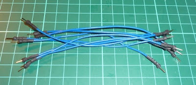
In no time at all, you can make a batch...
I enjoyed doing it so much that I went out to the local "cheap shop" and got a box for the new collection...
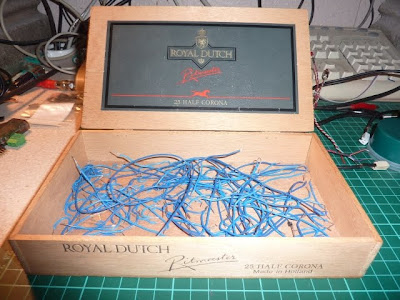
Looks nice, doesn't it. But it doesn't have the homely, "lived-in" quality of my old box full of bits of blue solid-core wire that I will continue to use on my solder-less breadboards...
Making breadboarding easier accelerates projects and makes more ambitious ones tractable. Now its time to get on and USE the new SOIC chip and the swanky new jumpers.
...-.- de m0xpd
The next steps of my digital implementation of the "Tube Screamer" require some different digital potentiometers. One of these was available only in SOIC packaging - hardly the thing to plug into one of my beloved breadboards. Unfortunately, I am too cheap to consider exchanging my shekels for a commercial solution to this problem. Fortunately, making one is the work of only a few pleasurable moments...
Here's a copper pattern if you want to make one of your own...
I etched a few onto a scrap of FR4...
and drilled and sawed them...
Now for the hard part - soldering one of these microscopic devices onto the new carrier...
It went surprisingly well, given my poor eyesight. All that was then needed were some legs to fit into the breadboard...
Whilst we're on the general subject of breadboarding, I may as well tell you about my new jumper wires...
I had always admired those nice flexible jumper wires you can buy in little sets - but once again, my healthy reluctance to spend money on old rope (or little lengths of wire, in this case) has prevailed. Until recently...
I cut up a few lengths of wire...
then I prep the ends...
... and gather together the other ingredients for this simple recipe.
These are terminal "pins" made from pieces of chopped up header plug and little lengths of heatshrink...
I solder on one end, add two lengths of heatshrink, then solder on the other end.
A little judicious stretching with the ends of a small pair of needle nosed pliers helps the heatshrink over the body of the "pin"...
... before it is shrunk down using that old cigarette/cigar/pipe lighter we no longer have any use for...
In no time at all, you can make a batch...
I enjoyed doing it so much that I went out to the local "cheap shop" and got a box for the new collection...
Making breadboarding easier accelerates projects and makes more ambitious ones tractable. Now its time to get on and USE the new SOIC chip and the swanky new jumpers.
...-.- de m0xpd
Sunday 16 December 2012
Tube Screamer goes digital
Having enjoyed playing about with the "Tube Screamer" guitar overdrive effect, I decided to experiment with a digital version. Purists need not panic - I don't mean anything vulgar like an embodiment of the effect in digital signal processing. Rather, I mean a digitally controlled analog Tube Screamer. This way, I get to keep the architecture and (hopefully) sound of the original "urban legend", but add flexibility of control, easily recalled presets and - one day perhaps - external control by MIDI.
Here's my initial experimental version, which I completed today...
The breadboard includes a standard Tube Screamer circuit (here implemented using two single (NE5534) op-amps to spread things out a bit) with the potentiometers replaced by digitally controlled resistor networks.
The whole shooting match is under the control of a big fat PIC 16F887 micro-controller - chosen because it has LOTS of IO lines.
Instead of the "knobs" there is a user interface comprised of a simple "keypad" and a 16*2 LCD Display. The keypad allows the user to move around a menu system, giving access to the "Drive", "Tone" and "Level" controls. One day (though I haven't implemented it yet) there will also be some default settings.
Here's some (poorly photographed) views of the menu structure...
The keypad and menu system were borrowed from that I developed for the m0xpd multi-mode beacon project.
At the moment, I'm experimenting with two alternative means of implementing the digitally controlled resistors, both of which emerged from the m0xpd "junk box". First, for the "drive" control, I'm using a 4066 quad bilateral switch, the elements of which can short a ladder of resistors in a "base 2" sequence of magnitudes (in so far as E12 resistors can approximate such a sequence), giving 16 different drive levels.
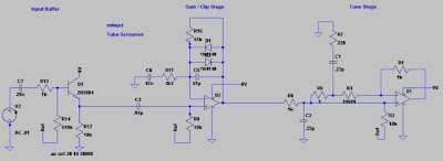
Here's the bones of the schematic...
The tone and level controls use pukka AD5220 digital potentiometers (the junk box does have some pretty high-class junk), with the level control made to have a log-like characteristic using Rod Elliott's "Better Volume Control" trick.
The whole thing works surprisingly well - more reports later when I add more sophistication!
...-.- de m0xpd
Sunday 2 December 2012
Phasers to Stun
Like her ovine eponym before her, Dolly the Tube Screamer has triggered an avalanche of cloning activity. Only a small avalanche. In fact, only one further clone. This time, the object of our sincere flattery is the MXR Phase 45.
I always wanted a phase pedal as a youngster, but somehow never got round to doing anything about it (the m0xpd wallet having been infamously dusty for a very long time). Now, however, flushed with the success of previous stompbox cloning activities, I decided it was time to take the plunge.
You can find the Phase 45 schematic all over the internet (I don't intend to stomp all over MXR's intellectual property by reproducing it here). The junk box dictated that I should replace the original 2n5952s with my default J-FET; the 2n3819. Whilst I was about it, I decided also to replace the two dual op-amps of the original with a single quad package - in my case a TL074 - making the PCB layout simpler...
The red line is a wire link on the component side.
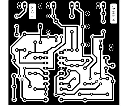
Here's the single copper layer at 600dpi (for my records only - I can't possibly condone any of YOU people making a copy!)...
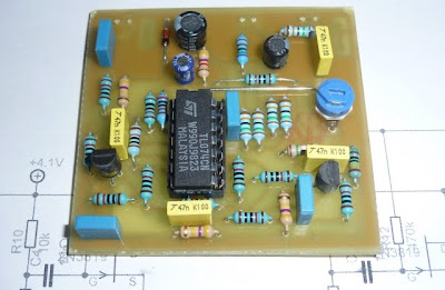
The assembled PCB looks like this...
It is a very tight squeeze to get it all into a Hammond 1590b-sized box (faithful to the MXR original). To be honest, I had to replace a couple of the caps shown above on the PCB with ceramics on the opposite side - don't tell anybody.
Anyway, after a good deal of cussin' and shoe-hornin', I got it together - here's a POV shot of Dolly the Tube Screamer (right) and her new friend...
The Phase 45 (in common with most similar effects) uses all-pass filter networks (two, in the case of the Phase 45) to achieve the phase shift implied in the name and sums the original and phase shifted signals together. This summation introduces constructive and destructive interference at different frequencies, which are swept around by the action of a low frequency oscillator modulating the phase shift.
In an idle moment, I found myself wondering how the all-pass network works and so, with the popularity (or at least, large number of page hits) of my recent Tube Screamer Analysis ringing in my ears, I decided I'd post the results of that idle speculation...
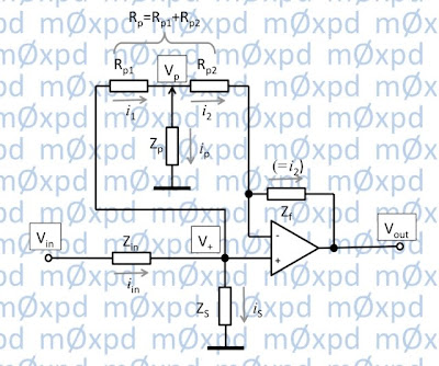
We start off with the generic active all-pass circuit...
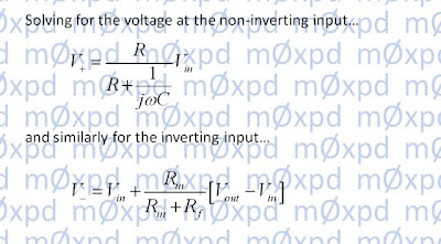
Then we use the potential divider rule to solve for the voltages at the op-amp's inputs...
At this point back in the analysis of the Tube Screamer, I glibly said "the action of the op-amp is to drive the voltage difference at its inputs to zero" (or words to that effect). This time, I'll be slightly less glib and argue that the op-amp multiplies - amplifies ! - the voltage difference between the inputs by a positive constant, "A"...
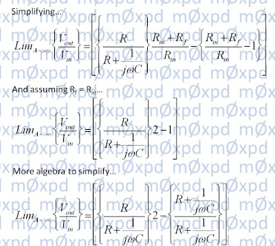
Now we can do a little algebra to simplify things, before asking what happens if the amplifier gain is very large - in fact, what happens as it approaches infinity. The mathematicians might call this sort of question "limiting behaviour"...
Once again, we'll keep tidying up the algebra and then we'll make the important assumption (as in the MXR Phase 45) that Rf and Rin both equal 10kOhms, in which case some further simplification is possible...
The final result (that result which is published all over the place) is then available after another piece of trivial algebra...
The numerator and denominator of the right-hand side of the equation above (i.e. those bits above and below the horizontal line), being complex conjugates of each other, have equal magnitude frequency response. Therefore, the magnitude response of their ratio is unity (all the changes in the numerator are exactly balanced by equal changes in the denominator). That is to say, all frequency components are unchanged in amplitude as the pass through the all-pass filter - it does what it says on the tin!
However, the network has a non-trivial phase response. In the Phase 45, this phase response is exploited by implementing "R" in the two cascaded all-pass filter stages by a network including a FET (one of my 2n3819s) in ohmic mode, with its gate voltage (and, so, the equivalent value of "R") modulated at a low frequency. This frequency is controllable by the external "speed control" seen on the original MXR product and on my clone.
I included a shopping link for the Phase 45 above because it really is cheaper to buy one than to build a half-decent copy. By the time you've gathered together all the bits, made a PCB and accounted for your own time at anything above the minimum wage, you have already spent more than the GBP 60 or so they want for a "real" one. Perversely, there will always be a few fools, like yours truly, who prefer to make one just for the interest and the fun of it!
...-.- de m0xpd
Sunday 18 November 2012
Analysis of the Tube Screamer
Recent fun-and-games with copies of the Ibanez Tube Screamer guitar overdrive pedal have got me interested in its function to the extent that I've made an analysis of its small-signal frequency response...
Anybody who is discouraged by maths can scroll past ugly equations - there are results of measurements and Spice simulations lower down in this post! You might also find this excellent description of Tube Screamer behaviour more to your taste.
Readers might find the suggestion that linear circuit analysis of the behaviour of an inherently non-linear device is worth performing or reporting ironic. However, one of the defining and differentiating features of the Tube Screamer is precisely the filtering operations it applies to the guitar signal (and non-linear functions thereof). Accordingly, understanding the linear aspects of this "urban legend" is useful - we start with consideration of the "Tone" stage...
This circuit is a (fairly) conventional first-order HF shelving network - adjusting the tone control boosts or lifts the high frequency content of the input signal. However, the presence of the 220nF in the low-pass filter seen in the dashed red box above complicates the circuit - so my analysis is needed. To keep the algebra tidy, I've simplified the picture somewhat (by replacing the paralleled 220nF and 10 kOhm resistor on the input by a single impedance ZS and by replacing the series 220 nF capacitor and 220 Ohm resistor between the potentiometer wiper and ground by a single impedance ZP).
It is also necessary to name some nodes and currents, to which the analysis will refer...
The first step in analysing the tone filter is to establish a relationship between the voltage on the tone control potentiometer wiper and the op-amp input(s)...
This relationship will be used in the subsequent solution, so we're giving it a name: "X"...
Notice that X includes some fixed elements (like the impedance ZP and the total resistance of the tone potentiometer, RP. However, X importantly includes a variable element, Rp1Rp2 ; X is a function of tone control setting.
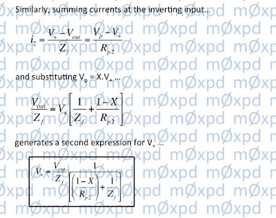
Our analysis proceeds by considering the currents at the op-amp inputs...
which leads us to a solution for the frequency response of the Tone stage...
Notice that this solution includes 'X' (which we already know to be a function of tone control setting). The solution in the form above is also itself an explicit function of tone control setting, through the presence of Rp1 and Rp2.
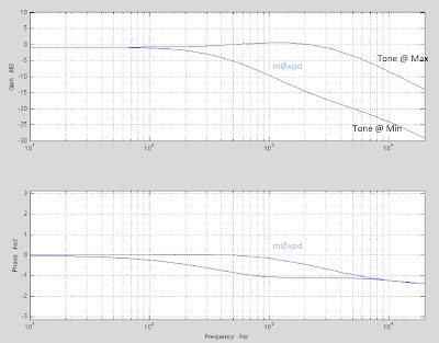
The response of the tone control stage alone is shown in the Bode plot below (produced in MATLAB, by evaluating the solution shown above). The result shows the tone response with the tone potentiometer in extreme positions...
Having solved for the response of the Tone stage, it is simple to go on to develop a solution for the overall frequency response of the Tube Screamer (at least in the small-signal context below the signal amplitudes that start to introduce distortion). Analysis of the "Clip" stage is actually easier than that for the Tone stage...
In the analysis which follows, we assume that the voltage over the diodes is lower than their forward turn-on threshold, in which case they can be ignored. The high-pass filter in the dashed red box of the figure above is loaded only by the very high input impedance of the op-amp's non-inverting input. We can, therefore, obtain its frequency response using the potential divider rule. Thereafter, the op-amp is in standard non-inverting configuration, such that its response is given by a familiar simple rule. The Clip stage small-signal behaviour can be written immediately as...
Various commentators have spoken of the action of the Tube Screamer being largely derived from the fact that the clip stage passes a mixture of the un-processed guitar sound plus the distorted sound - this is seen in the sum in the square bracket of the equation above. I confess that I'm not sure how useful this distinction actually is to understanding the system - particularly as Zf/Zin > > 1.
Now we have small signal responses of the Clip and Tone stages, we can multiply them together to get the overall response of the Tube Screamer (as shown in the equation at the top of this post). But who's to say my analysis is right?
Fortunately, there are ways to check it...
First, we can follow the lead of others and perform Spice analysis of the system...
Second - and much more interestingly, we can make measurement of an actual Tube Screamer (or, at least, one of my new clones) and compare the result. The graph below shows the magnitude frequency response of the Tube Screamer's small-signal (linear) behaviour, at extreme tone settings. Three traces are shown - one for my analysis, one for Spice modelling and one for actual measurement. You can see they overlay each other, equal (to within expected errors)...
The "Analysis" result in the graph above also includes a few high-pass responses, not described in the text. These are associated with (e.g.) the input and output buffers (implemented by emitter followers in the Tube Screamer) and have very low frequency corner frequencies.
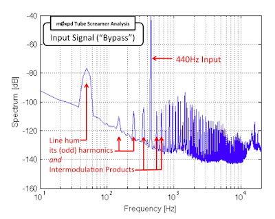
Having spent effort avoiding non-linearity (such that Fourier and Laplace have something to contribute to a small-signal analysis), I took the opportunity presented by having the Tube screamer (clone) connected to some heavy-weight analysis gear to record some of the system's non-linear behaviour...
I generated a 440Hz sine-wave test input. Non-musical readers may remember that 440Hz is an important frequency reference that used to be broadcast on BBC2 with the test card, before wall-to-wall daytime television crowded out the schedule. More musical readers will know that 440Hz is "Concert A"...
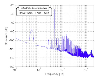
With the drive control and tone control on minimum, the output produced in response to the 440Hz input is little different...
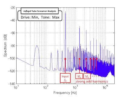
Turning the tone control to "Max" allows strong odd-order distortion products through to the output...
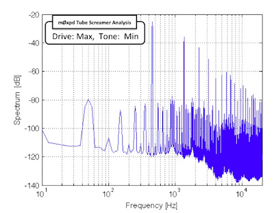
With the drive control on "Max", but tone backed off to "Min", there are still strong odd-order overtones produced...
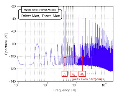
Finally, pushing everything up to eleven boosts the strong odd-order products and also allows some even-order distortion products to be seen...
OK - that's enough building, simulating, analysing and measuring. I really ought to be playing.
...-.- de m0xpd
Subscribe to:
Posts (Atom)

