Saturday 21 November 2015

Bridge Measurements

The little bridge you saw back in September is now producing - in concert with the AD 7896 analog to digital converter and a few other little wrangles - some nice, calibrated measures of reflection coefficient (and, in other programs, other metrics - but I'm only going to show Reflection Coefficient here).


Impedances under test are connected to the bridge at the point labelled "test port" in the photo above.

To start with - rather in the way of  the limbering up exercise that athletes do before they make any real effort - here's a measurement of the limiting cases of open- and short-circuit conditions...


Apologies for the poor photos - it isn't easy to photograph the little 2.4 inch TFT screen. In these limiting cases, the signal returned from the "perfectly UN-matched" termination is exactly equal to the signal applied; there is no return loss. The reflection coefficient (which is the negative of the return loss) is also zero. You see this zero result from 6 to 8 MHz in the plots above.

Next, the rather more interesting cases of a 100 Ohm resistor and the (perfectly matched) 50 Ohm case...


The theoretical reflection coefficient from a 100R resistor is -9.55dB, so you see the measurement is doing a pretty good job. The perfectly matched 50R resistor should give no reflection and a -inf reflection coefficient. I arranged for my graphing routine to clip everything to -40dB to neaten up the bottom of the (finite) dynamic range of my system (-40dB reflection corresponds to a VSWR of 1.02, so this is an entirely adequate dynamic range).

So much for "validating" measurements - what about real applications?

Here is a measurement of the reflection coefficient from the feeder to my antenna system at the shack, over the same frequency range, both direct and then tuned...


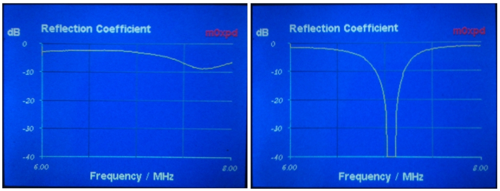
The system un-tuned (left) offers VSWR above 2. However, when seen through my "Made from Junk" MFJ-969, the  antenna offers a well matched load in the CW portion of the 40m band - just as my settings of the tuner asked it to!

This is now a working "measurement" system - if measurement isn't too grand a word. It involves a few neat tricks, which are going to be published in magazine / journal articles, so watch out for those in the usual places over the coming six months or so. There will be more to say in these pages on related issues as well.

Amazin' what you can do with a DDS and a diode!

...-.- de m0xpd


Sunday 8 November 2015

ADC Converter Accuracy in the Arduino DUE

I've been playing with the analog to digital converter in the Arduino DUE, using it to read the output of a simple RF detector. I am interested in measuring the lowest possible voltages with both the detector and the micro-controller.

There are some interesting behaviours at the low end of a diode detector's response - but that's the subject for another day. Today, I want to focus on the analog to digital conversion to read the data into the micro-controller...

I have found that the 12-bit ADC in the Arduino DUE has rather poor linearity at the extremes of its range. As I'm interested in accurately converting very small voltages (in the 0.01V range) to get best accuracy and dynamic range from my diode detectors, this is a problem.

Specifically, the response of the ADC follows something like the following deliberately exaggerated characteristic in the sketch below.


Instead of a linear relationship between the applied voltage and the resulting code from the ADC, suggested by the dashed line in the sketch, there is instead something of a sigmoidal shape, as shown in blue. This indicates inaccuracy in the analog to digital converter integrated into the DUE's Atmel AVR SAM3X8E processor.

To get round this, I tried hooking up a simple 12-bit converter from Analog Devices - the AD7896 (which just happened to be in the "junk" box). The resulting lash-up is seen below...


I wrote some code to drive the external converter (a listing of the function is given below) and then set up a test in which both the external AD7896 and the SAM3X8E were set to convert the same analog voltage. The results were converted from a code into a voltage (in milliVolts), allowing the performance to be compared with the voltage as shown on an external meter.

The poor performance of the DUE's internal converter is seen in the following images, in which the ADC results are photographed from the little colour TFT screen seen in the bench shot above and compared with the voltages as measured on a voltmeter...

At voltages below about 10mV, the DUE returns a zero result (but the AD7896 works FB)...


At slightly higher applied voltages, the DUE at least produces a non-zero conversion result - but it is below the true voltage (as shown in the sigmoidal curve falling below the ideal linear dashed line in the sketch of the conversion characteristic, above). Once again, the Analog Devices converter does a good job...


Here's the function I used to interface to the AD7896 - all simple enough...


The moral of this story - don't use the internal ADC of an Arduino DUE if you want accurately to measure voltages. My meter project just got a a little more complicated!

Interestingly, Tex Swann, g1tex, is talking about reading diode detector voltages into an Arduino (UNO) in the December number of Practical Wireless which  was delivered to m0xpd yesterday - but he is more interested in large-signal behaviour.

...-.- de m0xpd

Saturday 7 November 2015

Channel Separation in Parallel IF Receivers

The "Parallel IF" scheme, developed in this receiver, described in the January, 2015 edition of RadCom and described and demonstrated at FDIM 2015, steers the incoming signal in a superhet receiver through one of two Parallel IF filters. These two filters allow the rig to switch between receiving bandwidths appropriate to (e.g.) SSB and CW operation, just by change of IF frequency.

Whilst the theoretical separation between the two IF paths is high, any practical realisation will have only a finite degree of isolation - there will be some breakthrough on the "unintended" IF path when the other is in use.

This was noted in the RadCom article, which states: "Very little of the signal from the tuned station passes through the other, ‘unintended’ IF filter (whose response is drastically attenuated 2MHz away from its passband)." It has also been my experience in using the method - pulling the "operational" filter out of circuit (easy to do with my plug-in modular filters) effectively muted the receiver. However, I decided it was important to make some measurements to test this separation in a practical Parallel IF rig.

I used the plug-in BITX as the test platform, and applied a 7.03 MHz signal from a DDS, via an attenuator, directly to the antenna input...


I tuned the radio so as to achieve an output at 1 kHz and monitored the output voltage on a PC analyser called "Visual Analyser". I coupled the receiver to the PC soundcard using an isolating transformer, to reduce problems with mains/line hum.

Here's the system output as measured through the CW IF filter (which uses a 12 MHz IF path)...


I disconnected the input to the 12 MHz CW filter, leaving the IF set at 12 MHz and the other (10 MHz) filter in place. The input was still applied to the receiver. The response changed...


Note that the signal is now 48 dB down on the original - down in the noise floor. It is inaudible.

When I switched to the SSB IF filter (at 10 MHz), the signal re-appeared...


Note that it is matched closely to the level achieved through the other IF path (it is roughly 1.5 dB down), suggesting that the gains of the paths are well-matched (as confirmed by listening). However, the wider bandwidth of the SSB filter has admitted more noise and increased the level of harmonics of the 1 kHz signal (possibly as the wider filter bandwidth causes the stages after the filter to be driven harder).

Interestingly - and quite by accident - I discovered that  separation between the two IF paths was poorer if I completely removed one of the filters. Here's the response when the system is set to use the 12 MHz) CW filter, but that filter is removed...


The "breakthough", coming past the remaining 10 MHz SSB filter, is now only 36 dB down on the original level. Remember (from above) that when the filter's input was open-circuited, the residual was 48 dB down. Here, when the filter is completely removed from the circuit, the performance is poorer.

These measurements have confirmed my subjective impression - derived from experience - that a practical Parallel IF receiver (even one made within the poverty of my construction skills) can achieve channel separation entirely adequate to its intended use. It can also match the in-band gain of the two paths.

What a relief!

... -.- de m0xpd