Sunday 8 October 2017

Gaelic WSPRs

I was fortunate to spend a week on the banks of Loch na Deasport on the Isle of Lewis and (as previously advertised) I decided to throw out some WSPR signals.

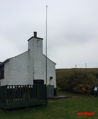
The cottage in which I was staying had a convenient 'fence-post' to support the telescopic pole I use to hold up the centre of my 'holiday dipole',


so I was soon in action on 20 and 40 metres.

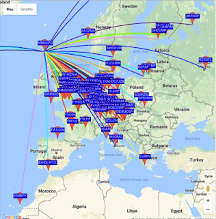
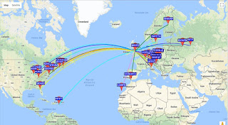
It was nice to see the 'xpd' lines on the WSPR map diverging from somewhere other than Manchester, for a change...


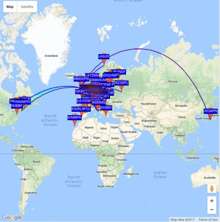
and my new /a location allowed me to reach places I'm not ordinarily able to cover from the home QTH (at normal WSPR power levels, at least), including some novel parts of Canada, the mid-west and Japan (the latter seen here)...


I did try a few CQ calls on CW, but wasn't heard, despite being spotted by the Reverse Beacon Network. This being an 'ordinary' holiday, I wasn't able to spend much time at the key trying for a contact - which was precisely why I left it with the WSPR mode.

Another important mission whilst on Lewis and Harris was to indulge in the delicious Stornoway Black Pudding, to which I was introduced when reading Alastair McIntosh's equally delicious book Poacher's Pilgrimage and which I've been eating (whenever I can find it) ever since. Being on Lewis gave me the perfect opportunity to visit the lodestone, so the xyl and I found three Stornoway butchers - each claiming to have 'original recipes' - and sampled their wares.

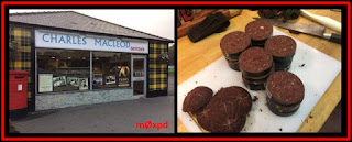
After careful tasting sessions, we found we preferred the offering from Charles MacLeod, whose shop (below left) is near the Co-Op on the outskirts of town. We purchased enough pudding to sink the CalMac ferry, which we have today sliced (the pudding, not the ferry) and put into the freezer in breakfast-sized portions, some of which you see below right...


Charles MacLeod is known locally as 'Charley Barley' - usual disclaimer. The other butchers and their puddings were good too.

You go into wild places like the Outer Hebrides to get away from it all - so you'll imagine my surprise when I was walking down a backstreet of Stornoway and heard a cry of 'Paul'! It was a fellow radio amateur, well known on the RSGB / G-QRP circuit, who I'd seen only a matter of weeks before at the Telford event and who had also taken exactly the same week 'away from it all' with his xyl.

Small world indeed.

...-.- de m0xpd

Wednesday 20 September 2017

iPad WSPR

I'm about to take a few weeks rest up in Bonnie M-Land. Since I always take the trusty FT817 on (domestic) holidays and am never far from an iPad or iPhone, I thought it might be fun to see if there is an iOS APP which could squirt WSPR signals out of my holiday antenna.

Sure enough, Federico, IW2MVI, has put together a terrific offering called iWSPR, which does the business. It is available for a reasonable fee on the App Store.


You can run iWSPR 'acoustically coupled' to your rig - but that is pretty much asking for trouble and it is so 1970s. I decided to look into lashing together a cable to connect the iPad to my '817.

Ordinarily, this wouldn't be a problem but for the fact that the '817 has no VOX on the DATA input and the iPad only offers an audio output. Consequently I had to derive a PTT signal from the audio output.

Federico offers such a circuit in notes supporting his software, using a FET to switch the PTT line. However, I wondered if a simpler solution would work.

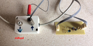
I threw together this circuit, in which the audio output is rectified by a voltage doubler. The same idea is used by many other dabblers, including Alan Yates, vk2zay. I found there's plenty enough AF output from the iPad to generate sufficient d.c. voltage to allow the BJT to switch the FT817's PTT line reliably (in my case the transistor was a BC557).


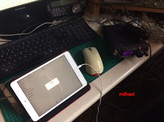
The little circuit is designed to be used with my existing 'dead mice' interface, which is seen next to it here - there's an extra connection to the PTT line via the big ugly red 4mm plug (I was in a hurry).


The whole kit was tested here on the bench at home before we pile into the car for the drive north tomorrow.


Putting out a lazy 5 W on 20m I was easily able to get all over the place, before throttling back to a more conservative and appropriate 500mW.


I hope to contact you from Scotland, either on WSPR or (perhaps) on other modes.

...-.- de m(m)0xpd

Tuesday 18 April 2017

Volca Sync DIY

A few weeks back Cameron (yes - the Cameron who started all this synthesizer nonsense) came into the office with a neat little toy. It was the Volca Keys Analog Synthesizer, made by Korg. It was great for annoying other occupants of the office (especially Tom) but it couldn't really do anything my modular couldn't already do (apart from in the sequencer department and I already had plans to put that right).

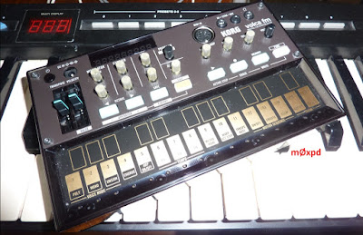
Last week, I found myself outside a music shop and I went inside and got myself another member of the Korg Volca family, which could do some different things; the Volca FM, which is a Digital FM synthesizer...


I spent quite a few happy hours over the Easter weekend putting right the deficit on my modular synthesizer by building the sequencer which I've been plotting for the last few weeks. Once I had that running, I thought it would be neat to synchronize the little Volca up to the modular, so the two can play along together...

The Volca FM (in common with the other units in the Volca series) has a couple of sync connections on its front panel: SYNC IN and a SYNC OUT, both on 3.5mm TRS jacks. The user manual explains their use and enough to deduce the 'format'...


The new sequencer for my modular synth is controlled by an Arduino (NANO) and has 5V clock signals bouncing around all over the place. But there isn't a  15ms pulse / trigger. Of course, I could generate one in software and output it over a GPIO but
  1. that would take up resources in the code and, more importantly, 
  2. I have already assigned all the IO resources of the NANO to other functions. 
So - I decided to generate the sync pulses from the existing clock pulses using hardware.

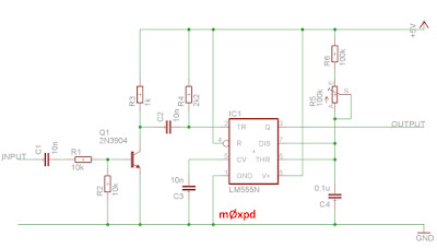
All that's needed is a simple one-shot, triggered at the leading edge of each of my existing clock pulses. Sounds like an easy job for a venerable 555.

Here's my circuit:


I put the trimmer on the resistor which sets the time constant as I didn't know just how sniffy the Volca would be about the precise length of the 15ms pulses (the total resistance should be about 137 kOhms for a 0.1uF capacitor). As it happens, I suspect a 100k and a (fixed) 33k in series would do fine.

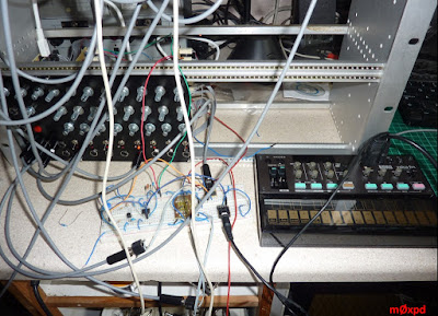
Here's the circuit in development on a solderless breadboard, with my sequencer off to the left:


Adjusting the trim pot allowed me to set the specified 15ms pulse length:


and here are a train of pulses, generated when my sequencer is stepping at its fastest rate (as currently programmed):


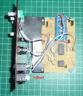
Here's the circuit at the bottom of my (working, but not-yet completed) sequencer controller module:


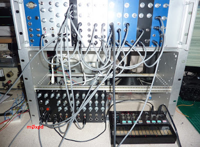
The whole thing clocks the Volca FM perfectly:


I can't test to confirm that the same circuit will also drive the other Volcas (because I don't have any) but I'm sure it would. Perhaps I'll ask Cameron for a loan of the Keys, just to be sure.

Now I need to arrange for a clock input to my sequencer to respond to the SYNC OUT of the little Volca - it only seems fair.

...-.- de m0xpd


Sunday 26 February 2017

Signal Processing on the Arduino

I've been doing some DSP on the Arduino


Since signal processing is so computationally intensive, we tend to associate it with powerful processors, like the mighty ARM of the DUE. However, it is entirely possible to do useful signal processing tasks - such as running digital filters, or even performing Fourier Transforms - on humble little processors like the ATmega328 on the Arduino. These past few days I've been doing just that.

The application is within music - specifically, on my new modular synthesizer. But don't look away just because you might not be interested in music, for underlying this is an entirely general application of real-time programming.

My synthesizer already had (as you might have seen) a couple of envelope generators, capable of producing exponential 'attack' and 'release' envelopes at the edges (or at the beginning) of a gate pulse. However, I wanted a more traditional 'ADSR' envelope generator with the capability to generate independent control of three time constants: attach, release and 'decay', as well as to manage the amplitude of a 'sustain' phase.

This type of circuit needs two core elements:
  1. a first-order circuit with three controllable time constants   
  2. logic to switch between the three exponential decay phases and manage the 'sustain' phase.
Ordinary ADSR circuits charge or discharge a capacitor at three different rates; an analog solution involving a simple, first-order differential equation (albeit with changing coefficients). The exponential voltage required in any phase is the voltage on the capacitor of a trivial RC filter.


It struck me that - given the requirement for the logic around the analog filter, the entire system might be better implemented by a micro-controller, replacing the analog 'filter' with its digital equivalent.


I certainly don't claim any novelty in this thought - indeed, it was reading about Tom Wiltshire's excellent Digital Envelope Generator which motivated me to give it a try. But the experiences of doing some more work back in PIC-land last week (more of that in a later post) reminded my just how dry and tedious that place can be, so I set about trying it on the homely little Arduino.


Neither do I claim any novelty about the idea of doing it on an Arduino - somebody/several bodies must have done it on this platform before (indeed, I got a first version running using ADSR() from Mozzi, but I didn't like that for several reasons, most important of which was management of the sustain phase). Anyway, whatever the reasons, I wanted to have a bash for myself.

Let's take a look at my code first.

Here's the core first-order difference equation which - in any of the phases of operation - produces the required exponential envelope...

'envelope' is the main variable, which is updated every pass through the program to its next value, ready to be output to the DAC in the 'Set_DAC_4921()' subroutine. 'alpha' is actually the location of the single pole of the digital filter (remember - this is a first order digital filter) and it determines the 'time constant' of the exponential decay. 'drive' is a constant, driving the step response of the filter in this phase. The factor (1-alpha) is required to correct the overall gain of the filter to unity at zero frequency.

If you don't understand the math behind this stuff don't worry - you can read about it in a book if you like - or you can just be content to use the results. I've written the difference equation in the comment above in something close to 'conventional' notation, for those who do understand these things.

That was the first of the two 'core elements' - the digital filter implementing the exponential response. The second part is the logic. Here's a snapshot of part of that logic...


To be precise, it is the part of the logic which tests if the envelope is at the end of the attack phase. If it is the end, new values of 'drive' and 'alpha', relevant for the next phase - the decay phase - are loaded.

Enough dry talk of the inside of the code - if you want to see it all, you can download it from this github repository.

I had to give it a name and I followed the rather childish practice of choosing names which pick up on the involvement of the Arduino: 'ADSRduino'. Sorry.

Instead of talking, let's see some action.

You probably weren't impressed with the rather quantized image at the top of the post. What you didn't know was that entire envelope was less than 10ms long (shown in order to demonstrate that this system is appropriately fast - in fact, the sample rate [that's to say, the rate at which the difference equation is operated] is around 3.3kHz).

Here's a longer event (around 400ms long) along with the gate pulse from my keyboard which triggered it. It leaves time for envelope to move through the quantization steps of the DAC more slowly, making for a smoother trace.


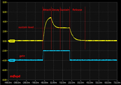
Here's the same thing, annotated to make it clear what all this is about:


You can see that the attack phase starts when the note is gated and rises up to full value (actually 5V) then falls down in the decay phase to the sustain level. The note is sustained until the gate is released (unless it already has been released), after which the release phase begins.

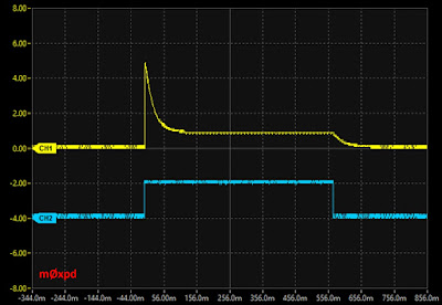
The time constants for attack, decay and release - and the level for sustain, are adjustable via user potentiometers. To illustrate the point, here's another setting (with fast attack and lower sustain and, as it happens, I pressed down the key for longer, so the gate pulse and associated sustain phase is longer):


All of this is actually running on useful hardware. It started as a prototype on an Arduino UNO and then migrated onto a physically smaller NANO, which is seen here...


You can see both the original trimpots used for the ADSR controls and the new potentiometers on a front panel (made from double-sided copper-clad board, painted black to make it look fancy) - as well as sockets for the gate input and the output. There's also a switch to select a looping mode, in which the system can automatically re-trigger itself.

You can also just see (at the right-hand end of the breadboard) the little MCP4921 12-bit DAC used to output the envelope voltage.

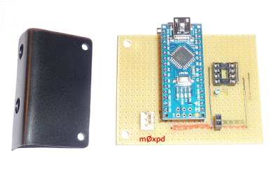
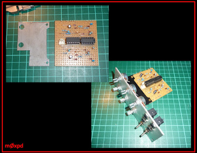
The circuitry above was moved onto a piece of stripboard:


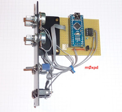
and assembled, using the bracket bent up from sheet steel, into a complete 'Eurorack' module:


You can find a schematic for the whole system here

It now does great service in the considerably extended modular synthesizer:


where it sits next to another Arduino-based module, running as a voltage-controlled digital wavetable oscillator, built upon resources from the Mozzi library.

Of course, as I mentioned at the top of this post, you can take the signal processing ideas on the Arduino further than first-order. I've been playing with a biquad structure on the Arduino within the loop() function...


(in which all the elements have their usual meaning). I found that it is easy to achieve a sample rate of 2 kHz which - although it isn't useful for audio frequency work - does make for some very useful filtering for signal detection etc. If you need to detect or monitor AF signals, the Fast Fourier and Hartley Transforms work very well at sample rates of tens of kHz - but that's a rather different kettle of fish.

Don't overlook the little ATmega328 when you're playing with a time-varying signal that takes you to the edge of a DSP application. You can run some genuine digital filtering algorithms (including floating point math to manage poles right up close to the unit circle) and have fun in the process.

...-.- de m0xpd
Saturday 4 February 2017

A Modular is Born

I should 'fess up'. I've been having a ball. I've been neglectful of the radio arts whilst working up my recent experiments with analog synthesizer elements into something more permanent.


In fact, you caught a glimpse of some of my synth modules on stripboard in my last post. Now, I've bent up some mounting brackets from sheet steel and made front panels (in standard 'Eurorack' size) to turn them into pukka modules.

Here, for example, is the evolution of my dual envelope generator module, the circuit of which was inspired by ideas on Ray Wilson's MFOS site...


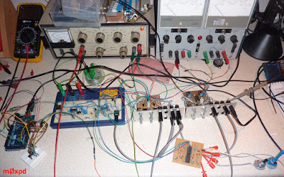
Of course, once in these modules, bringing together some recipe on the bench isn't quite as untidy as it was before


but the real purpose of adopting the (3U) Eurorack standard is such that everything can be mounted in a standard card frame.

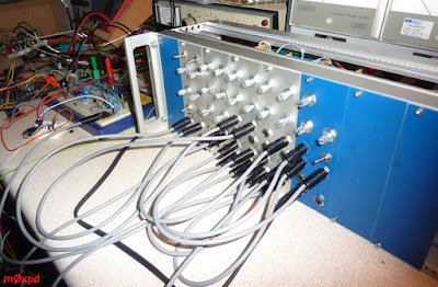
This ought to pose a challenge for a notorious cheapskate like m0xpd but - as ever -  it isn't what you know, it's who you know. In this instance, we're indebted to Nigel. A little judicious metalwork (to reduce the depth of the donor frame) and several modules later...


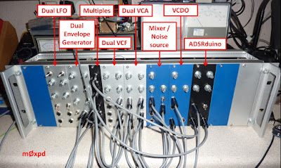
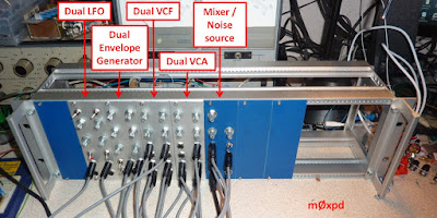
Here you see the current complement of modules, as labelled. With all the inter-connectivity afforded by those 3.5mm jack sockets, you very quickly learn the first rule of modular synthesizers: 'you can never have enough patch cables'.


Again, a challenge for the cheapskate (have you seen how much they want for patch cables?!?). Fortunately, I found a nice OM who is selling batches of old-school mono 3.5mm jack plugs on that familiar auction site for bait money - so I'm rolling my own patch cables.

In the image above you can see that the VCO is still in proto form, off to the left of the synth, because I'm still not happy with the performance of this simple oscillator with its (admittedly) simple circuit.

At least I've added a MIDI interface to drive the synth...


MIDI (from either a keyboard or from a sequencer on the computer, via the USB - MIDI interface) goes through the MIDI to TTL converter shown (which I knocked up with a 4N25 found in the junk box) and into the Arduino MEGA.

It is good that it's a MEGA because this flavour of Arduino has four UARTs, meaning that I can keep the connection to the PC (for e.g. programming) AND have another serial connection dedicated to MIDI. This isn't possible on (e.g.) the humbler Arduino UNO.

The Arduino MEGA is now running a MIDI to CV and Gate routine, with which I can make my new modular synthesizer generate all sorts of irritating and occasionally musical sounds.

So - not much radio action to report - but a whole lot of 'radiophonic' fun.

...-.- de m0xpd

Sunday 15 January 2017

Synthesized Sidetone

The m0xpd bench is full of even more tangles of wire, associated with analog synthesis.


I realised this morning that my new system could be gated by any time sequence, such as that produced by my Morse keyer - it is Funky after all! So, I've made the most over-engineered sidetone generator ever.

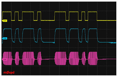
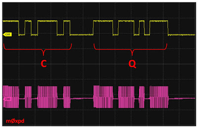
Here's the beginning of a 'CQ' call...


The top trace is the keying waveform, sending the letters C and Q (identified in red for the illiterate amongst you). In the bottom trace is the resulting audio; a 600 Hz tone, produced by the VCO,  modulated by new elements on the bench.

Since last time, I've made several new bits of what I've decided will be a modular synthesizer. The voltage-controlled filter, which languished on a solderless breadboard, has now been proudly copied onto a piece of Vero stripboard. In fact, there are two of them in a dual configuration. The VCF is filtering the (square) VCO output to make a cleaner signal for our sidetone (analog synthesizers generally use 'subtractive', rather than 'additive' synthesis).

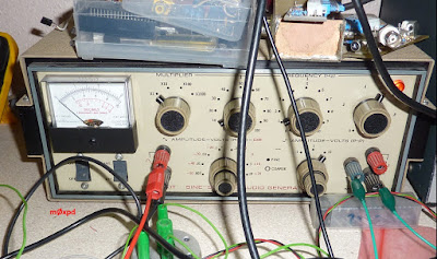
Next, I made a dual low-frequency oscillator on a piece of Vero, to save my trusty Heathkit AF generator from doing all the modulation duties. It isn't being used in this 'demo'.

More importantly, a look in the junk box revealed a nice crop of CA3080 Transconductance Amps - so a search on the web found ideas for a Voltage Controlled Amplifier, now implemented on another solderless breadboard. This is what is doing the modulation of the (audio) carrier you see in the image above to generate the 'CQ' sound.

Then, I've made a (dual) envelope generator, which makes exponential 'attack' and 'release' profiles at the beginning and end of gating pulses (or, alternatively, of triggers), which can control the VCA. This would usually be controlled by (e.g.) the gate output of a keyboard or sequencer - but in this silly 'demo', my morse keyer is gating the VCA.

Setting the attack and release times to take non-zero values allows the hard-switching of the audio seen above to be replaced by exponential gating...


The image above shows the output of the envelope generator in the middle (blue) trace.  This output is used as the control voltage for the VCA, which implements the modulation resulting in the trace seen at the bottom of the image.

Taking it too far, for example by setting an inappropriately long release time, reduces the modulation depth of the CW...


This 'soft-switching' of the sidetone takes away the hard, clicking edge associated with simple on/off switching, leaving the resulting waveform easier on the ear [for reasons directly analogous to those which motivate soft keying of RF to avoid spectral splatter]. Readers of long standing might recall that this is something I've played with before in building one of my keyers.

Here's a view of the modules of the synth in the making on the bench, with the modules and some other elements labelled...


You can see the Attack and Release controls. You can also see a small interface circuit to link between the (open collector) output of the keyer and the 12V positive logic required for the gate input to the Envelope Generator. This is a trivial single transistor.

The mess on the bench does allow half-way serious demonstrations of keying. But you just can't help applying frequency modulation to the CW and all sorts of other zany effects. There's music in there somewhere!

I've just come back from the West Manchester Club's Winter 'Red Rose' Rally. It used to be held conveniently close to my home, but now it has moved out to Lowton on the East Lancs. I was hoping to get some bits for the synth-to-be, but the Rally was a wash-out in more ways than one. No matter - I know where I can find lots of traders happy to send me all the pots and sockets and other hardware I need to put my circuits into Eurorack compatible modules.

...-.- de m0xpd

Sunday 8 January 2017

Analog Synths

Cameron was talking about analog synthesizers last week and he got me interested.

I refer, of course, to my colleague Cameron and not to the former 'Prime' Minister. Don't expect any political comment or porcine quips - that really would be beneath me...


There's quite a lot of common ground between me and analog synths: electronics, music, signal processing, some of the particular technologies of radio (modulation etc) - I could go on.

Despite this affinity, I realised when Cameron showed me some YouTube videos last week that, whilst I know all about the technology underpinning Analog Synthesizers, I've never actually played with them. So - you can guess the rest.

Yesterday I made a new mess on the bench...


The heart of the story is a Voltage Controlled Oscillator, which makes square- or triangular-waves, whose frequency is controlled by a voltage (hence the name). Now - we've done things not a million miles different than this before - but this is an audio project!

There's lots of circuits for audio fequency VCOs on the internet, but I wanted something which was not just a voltage controlled oscillator, but rather the particular sort of VCO used in a 'real' musical synthesizer. These have oscillators whose output frequency is proportional to an exponential function of the controlling input voltage (because then, the input voltage will be proportional to the musical 'note' produced, which is itself the logarithm of the frequency). These are usually called 'one Volt per octave' oscillators, because of one industry standard (used by Korg, Yamaha, etc) of using a voltage change of one volt to signal an octave change in frequency (a 2:1 frequency ratio).
 
I took as starting inspiration a circuit found on this page. Here's my resulting VCO...


As usual, I had to make various changes to accommodate the contents of my junk box (the linear to exponential converter stage is built on a TL074 and the VCO proper is an LM324). Plus, the final output was rather more than one octave per volt, so I've added some trimming, as seen. There's a potentiometer to manually tune the oscillator and two inputs for control voltages (CVs) - which are additive signals (i.e. you can transpose by adjusting the tune control).

I soon confirmed I could test the oscillator with the manual tune control and apply modulation input from an oscillator to get vibrato effects. Throughout all the experiments here, my old Heathkit AF Sig Gen was serving as the LFO and modulation source...


I don't have any analog synths or 1V/8ve gear, so I programmed an Arduino to make a simple sequencer.

You can't use the PWM output produced by the 'analogWrite()' function (at least you CAN use it, but you hear too much of the PWM frequency to make the approach useful), so I added an MCP4922 DAC (which I've played with many times before) to give steady DC control voltages and to increase the available resolution to 12 bits.

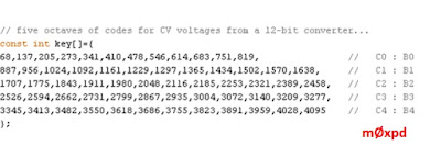
With the 12-bit resolution, you can easily construct a table of the codes required to put out five octaves of semitones...


from which a simple look-up allows you to sequence a loop of notes or a random pattern. I even added an analogRead() of another external voltage to control the speed of the sequencer. This sounds interesting when you control it with an LFO - especially when it is playing a random pattern. Funny how the 5V Analog Ref of the Arduino works so nicely with the CV scheme of the Analog Synth world.

The simple VCO tracks well over a middle octave and is very stable (particularly as I've not yet taken ANY steps to ensure temperature stability), but isn't going to knock Moog off its pedestal quite yet.

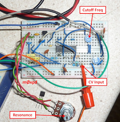
Flushed with the success of the VCO, I built a Voltage Controlled Filter, taking my lead from Outer Space and making the appropriate revisions to accommodate the contents of the junk box (most importantly to work in the beloved 2N3819)...


The filter allows you to make all the expected 'Wah-wah' type sounds and more, controlled manually or - more importantly - by external control voltages. These allow either continuous modulation (e.g. controlling the filter from a free-running oscillator) or can be triggered by the sequencer (e.g. I've set the sequencer to set a digital line LOW every time the root note of a sequence is played, which allows the filter to emphasize that note and - hence - the tonality of the sequence).

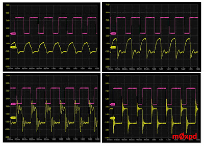
Here are images of the filter response (to a square wave generated by the VCO, set manually to 100 Hz) with varying settings of the filter 'cutoff', at full 'resonance'...


So, with only two simple analog circuits and a sequencer made from an Arduino, a DAC and a few lines of code, I've had quite a bit of fun. I guess the next step (if I can be bothered to make one) is going to involve a VCA, an envelope generator and a homebrew MIDI : CV converter.

Alternatively, I might just follow Chick Corea's advice and condemn these horrible pieces of electronics to where they belong and play a real instrument (even if my 'Hammond' is a clone)...


Or, I could even get back on the radio - let's see if that contest has finished yet...

...-.- de m0xpd