Sunday 22 February 2015

Arduino SDR Tx I

Tinkering at the bench this weekend has seen the focus of attention shift back to software defined radio. I am satisfied with operation of my stand-alone Arduino DUE-based HF receiver, but now it is time to look towards transmitting.


Fortunately, a transmitter is to large extent a receiver operated in reverse - so I hope to re-use a lot of the investment I already have made in developing the code for my receiver in building a transmitter.

Specifically, I plan to share the same IF architecture, with a mix from audio frequency to a parallel pair of IF filters with real-time adjustable bandwidth. One of these filters also implements the 90 degree phase shift of the Hilbert Transform, such that my subsequent mix up to RF using "Tayloe" methods can benefit from side-band cancellation.

Here's my first attempt, in which you can see the Arduino DUE at stage left, with the necessary supporting electronics on a solderless breadboard toward the middle of the photo.


The in-phase and quadrature VFO signals for the mix to RF were derived from the Kanga VFO system (which readers will recall hosts a Kanga / m0xpd DDS Shield which itself features a quadrature clock generator, to derive quadrature signals at a quarter of the DDS Module's square wave output). The "divide by four" and the limited bandwidth of the DDS Module itself imposes a limit of the practicality of this arrangement (to 40 or 30m), as Bill Meara recently reminded me - so I decided to switch to a Si5351-based VFO for further experimentation.

The photo above shows that the RF output is fed to my "Ugly Sudden" PA (because that was literally the first amplifier that I found in the drawer) the output of which was dumped into a dummy load.

Here's my second experiment, now with the quadrature VFO signals coming from an Si5351 (on one of the prototype Kanga / m0xpd / n6qw Si5351 Shields)...


As you can see, I started testing with a (literally) keyed sinewave.

Here's the overall architecture...


Everything on the Arduino DUE (i.e. inside the blue dashed line) is digital signal processing - the remainder is conventional physical electronics. The AF input is mixed up to IF, where it meets the two IF filters. Note that the IF filtering happens in the frequency domain (as denoted by the red background) - there's a Fourier Transform between the green and red areas. The filters are implemented block-wise by fast convolution. If you don't know what that is, don't ask!

The two filters have real-time adjustable bandwidth, as was described here, and validated by measurements here. Further, one of them has the additional 90 degrees phase shift over its pass-band associated with an approximation of the Hilbert Transform.

After Inverse Fourier Transform back into the time domain (at IF), the filter outputs are re-assembled from the block-wise form (using overlap-add) and output from the Ardiuno DUE's DAC channels. These outputs are amplified and passe to a Tayloe mixer, fed from QI VFO signals from the Kanga Si5351 board, to make SSB at the desired RF frequency.

My SDR code is not public domain and is not going to be released in the near future. There is a little description in the slides associated with my 2014 G-QRP Rishworth Mini Convention Presentation "Stretching a Point", but that's all that's going to be disclosed the the moment - so please don't bother asking.

In writing the new extensions to service Tx, the only non-trivial part of coding (over and above what I'd already done for the Rx) was the mix to IF...

The mix currently is implemented in the time domain (the green part of the graphic above). I guess it could be done by shifting the results of the Fourier Transform, but that is probably more computationally intensive. Simply multiplying the input AF signal by a cosine (at the intended "BFO" frequency) works...


however, the cosine function is so slow that - although the mix to IF works - the processor is taking so long doing this that it doesn't have time to complete the rest of the required processing (IF Filtering, IFFT etc) in the available time.

So, I switched to an alternative using modular arithmetic, conveniently available since my IF is at a quarter of my sample frequency (as you saw above)...


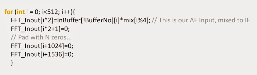
where I'd already defined the four possible values of "mix" as follows...


It is only when you come to write all this down on a blog page that the folly of using the word "mix" as a name for an array (when it is also used for the verb meaning "to modulate, multiply or heterodyne") occurs!

The modular arithmetic approach is fast and works well.

Here's a close-up of those physical parts of the system that are not digital signal processing...


which emphasises just how simple this approach is.

For convenience, I also threw together a new piece of code to drive the Kanga Si5351 shield - especially to provide a quadrature VFO output - here's a shot  showing that system in operation on 20m (ignore the bottom line - I was actually still in LSB)...


Here I was testing with not just the keyed 600 Hz tone (for CW Tx) but with voice input (actually it was Patrick Malahide reading Chapter 2 of Five Red Herrings - which just happened to be on my computer), which sounded nice on 20m!

So - this works. But you'll notice I called this post "Arduino SDR Tx I", suggesting there might be a part II, II, IV, etc...

In fact there is quite a "to do" list ahead of me - but I can now see a clear path to a stand-alone (i.e. PC-free) HF transceiver based on the Arduino DUE for CW and SSB. I know (because I've already had the Rx code running on an STM32F4 Discovery Board) that this will also run on some other ARM systems, which will offer some interesting opportunities for playing with price and performance.

Exciting times.

...-.- de m0xpd

Saturday 14 February 2015

More Rx Bandwidth Measurement

Way back in 2011 I published a design for an analog AF CW filter in SPRAT 146...


The filter was slightly unusual (i.e. it was differentiated from the thousands of other CW filters that already litter the literature) in that it used a gyrator.

It was designed to offer the user a single bandwidth control, which adjusted only the receive bandwidth without changing centre frequency, gain etc.. This (as those of you who play with filters will realise) isn't so easy to achieve, as all the parameters of a filter are interconnected, such that adjusting just one is not as easy as it might sound.

The filter works FB - as measurements of its frequency response, included in the original SPRAT article, testify. The magnitude response at a number of (arbitrary) positions of the "bandwidth" control is shown here...


The filter first was used with my Funster Plus rig, was featured in the Occam's Microcontroller" rig and was reprised in the "Occam's Dagger" rig, where it turned the otherwise rather wide open "d.c. to daylight" frequency response of the Sudden-derived receiver into a more practical proposition.

Well - the Sudden Rx shield is receiving renewed interest, as is the Occam's Dagger rig (a result of my recent demonstration that the Sudden Rx and Tx shields will run FB on the new prototype Si5351 shield). PLUS I have recently demonstrated a technique to directly measure the overall receiving response of a receiver, from RF to AF.

So, with this background and renewed interest, it seemed like a good excuse to look again at the response of the m0xpd CW filter in-vivo.

Here's the measurement set-up on the bench...


As you see, I am using the same arrangement as before. An Arduino (MEGA) generates an RF sweep from a Kanga m0xpd DDS shield, which is passed via an attenuator to the antenna input of the Radio under Test - in this case Occam's Dagger with the m0xpd CW Filter. You can just see the Rx Bandwidth control to the left of the Occam's Dagger rig.

The AF output from the rig is tapped at the speaker output and the (entire) AF signal is detected by the Bruel and Kjær electronic voltmeter, operating as an RMS to dc converter. The resulting dc level is fed back to the Arduino MEGA, which passes the value (along with the frequency to which it is associated) back to a Processing sketch, running on the PC, which graphs the result in real time.

As a base-line, the "native" response of the Occam's Dagger rig is seen in this response measurement with the CW Filter in bypass mode...


As I have explained previously, the abscissa of the graph above describes a 10 kHz RF sweep (from 7.03 to 7.02 MHz). The receiver was operating in lower sideband mode and was tuned to 7.03 MHz, so this will map to an AUDIO frequency range of 0 to 10 kHz.

As you can see from the above, the Occam's Dagger rig can be tuned at 7.030 MHz, and yet I can hear several kHz-worth of CW signals all at once (despite the low-pass slope, which does little to block big gun signals). There is essentially zero selectivity, save that of my ear/brain's ability to discriminate CW signals at different pitches!

Switching in the CW filter and advancing the bandwidth control to the tightest (practical) bandwidth produces the measured result shown in the graphic below...


The bandwidth control is seen to change the response dramatically, giving selectivity (indeed, too much selectivity sometimes, at such an extreme setting).

In fact, the change is continuous, between the limits of the graphic above. Some sense of this continuous change is communicated by the following sequence of measurements, each made at advancing positions of the Bandwidth control (reading down columns, then from left to right)...


Actually, the Bandwidth control can be moved to settings giving even tighter bandwidth - but these are achieved at the expense of increased noise and so are not used. Such a setting is shown in the measurement below, in which both the high Q-factor of the peak and the noise are visible.


So, just as was seen for the software defined radio (with its programmable Rx bandwidth) and for the Parallel IF radio (with its switching Rx bandwidth), this DC receiver is proven to have variable receive bandwidth as measured directly from RF input to total AF output.

I love this method for its speed, simplicity and honesty.

...-.- de m0xpd

Sunday 8 February 2015

Online I.F. Alignment

This post presents some new code to allow Online Alignment of single conversion receivers which use digital RF Generators and my Arduino code.

The original "RF Generation for Superhets" scheme (SPRAT 158) featured two digital oscillators under the supervision of a microcontroller, by which the oscillators could be "interlocked" to ensure the dial frequency was correct...


The SPRAT article promised:

"The ability to tune the BFO will be found of great benefit in the alignment phase of the development of a new scratch-built rig (which usually will feature a homebrewed crystal IF filter of uncertain passband). It allows the BFO frequency to be precisely optimised for the filter and leaves the builder totally free to set IF frequency to any value suggested by available crystals etc.."

Promises are all very well, but there comes a point where you have to deliver - otherwise they are seen as nothing more than empty promises. That point had arrived...

My co-conspirator Pete Juliano, n6qw, was struggling setting up another instance of the Parallel IF rig on the "left coast". The greater part of his problem was in setting up the system for some homebrewed IF filters. I felt for him - and realised that I could make things simpler by implementing an ONLINE alignment tool within the code. Pete was excited by the idea, saying that he was looking forward to "getting the radio working properly with BITE (Built In Test Equipment)".

The original approach required that some measurements of IF filter response were made and then the necessary BFO frequencies were entered into the Arduino sketch, which was uploaded to the chip and then tested. This approach is very much OFFLINE.

Instead, I have now added a further menu option (with apologies to all - including Pete - who think Menus are the work of the devil) which allow ONLINE adjustment of the BFO...

You simply turn on the radio and listen to how it sounds - if you want to try a different BFO setting, you enter the new BFO menu, adjust the rotary encoder and the system will change the BFO and the VFO to keep the incoming station in tune.

You can hear the change in real time. This is working ONLINE.

Here's the adjustment window on my Parallel IF rig (where it takes place on Menu 5),,,


As you see, I was on 40m in lower side-band (using the nominal 10 MHz IF).

The cursor indicates that any rotary encoder input will cause a change to the BFO frequency - NOT to the dial frequency (which stays on the display, reminding me that it is held constant as things audibly change).

Unfortunately, I could only arrange for the encoder to advance the BFO in fixed increments (as I don't have many push buttons etc on my rig - the to available push buttons are used to move up and down the menu system and if I tried to use them to change the cursor to another "power of ten" on the BFO frequency, it would move me out of Menu 5). Nil desperandum - I simply set the encoder to change the BFO in 50 Hz steps, which seems to be a useful, practical compromise.

When you're done playing with the BFO adjustment, you just step out of the Menu system (by pressing the rotary encoder's integral pushbutton) and the new value of the BFO frequency is retained.

There's a second BFO frequency for USB operation - if you enter the BFO adjust menu in that mode, it will automatically adjust the appropriate value.

Of course, my Parallel IF rig has two IF paths, each of which can run LSB and USB - so there are four BFO frequencies. Again, the correct BFO is "indexed" according to the mode in which the BFO adjust menu is entered, as in this example, where I was using the nominal 12 MHz CW IF path, again in LSB...


If you find you prefer an adjusted value to the "default" setting that is in the sketch, you can note down the adjusted value and change that default setting "Offline". Next time, the rig will be just as you like it. A useful piece of "built in test equipment" indeed. However, after having this feature in place, I wonder if there might be a place for keeping it with more than the test / development phase in mind.

In QRP applications, particularly in SSB, there are some marginal cases where the ability to change the IF tuning to throw away some wasted power in the low register of the voice might be useful.

I have added the Online Alignment feature to the RF Generator code for the pair of AD9850 modules (Double_DDS_VFO_0v3.ino) and for the Si5351 device (Si5351_VFO_0v3.ino), both of which can be downloaded from this repository. Users will find that the BFO adjustment menu is (in this case) Menu 4 (there being fewer menus than with my Parallel IF rig).

Please send your comments and observations if you experiment with this new code.

As for Pete's feedback on the system - I'll leave it to his own words:

"The BFO trim reminds me a lot of Pass Band Tuning that back in the vacuum tube days was available on just a few radios. So Bravo – now that I have found the BFO frequencies I can go back and adjust the sketch."

Seems he likes it!

If I had done this properly, I should have used the Arduino's EEPROM memory to store the BFO frequencies - but

1) I'm too lazy
2) I'm concerned about inter-operability between UNOs, MEGAs, DUEs ec (with their different processors and incompatible "EEPROM" provision),
3) I'm only trying to get across ideas here, rather than produce polished solutions
and
4) I really am too lazy!

Talking of doing the job properly, I wonder if you have seen Colin, m1buu's BITX20?

There's a great video of Colin's first QSO on the new-born rig, which Bill, n2cqr has mirrored up on the SolderSmoke blog.

Colin's homebrewed creation is beautiful - putting my own untidy efforts to shame - as you see in the photo below...


Colin's rig is of personal interest because it uses my VFO code, driving an AD9850 module.

Colin tells me that it was Pete (mentioned above) who sent him "an email stating the case for an Arduino / AD9850 VFO instead of the traditional L/C design". Pete gave Colin the code (essentially a version of my Kanga VFO code) and details of the n6qw hardware, a Pro Mini clone and the AD9850 Module, all mounted on a proto board, the wiring of which Colin followed. You can see this "digital" element above the display in the photo of Colin's FB rig.

As you can see from the photo and the concrete proof of the QSO in the video, Colin's rig is a great success - well done!

Colin reminds me that I persuaded him to buy an Adafruit Si5351 breakout board at the Rishworth Convention. Well - that board certainly would give a power saving over the DDS module for your SOTA work, Colin and - who knows, I might even persuade you to try using the digital BFO as well. Not that there's anything wrong with your present crystal oscillator!

...-.- de m0xpd


Sunday 1 February 2015

Occam's Si5351

This post describes the application of the Si5351 in a simple QRP CW transceiver from the "Occam" series of rigs...


The recently described Si5351 system under development is intended to be a development of the Kanga / m0xpd DDS Shield and to offer backward compatibility with that system. One of the important features of the DDS shield was the "RF Bus", by which RF signals were passed to other shields in the beacons and rigs arising from the "Occam's Microcontroller" project.

To achieve backward compatibility, the new Si5351 system has an enhanced RF Bus, using a double row connector, one row of which is in the same position as the single row on the original DDS Shield...


This allows e.g. the header pins of the Kanga / m0xpd Sudden Tx Shield to plug into the new Si5351 board and to run as a beacon transmitter system. As part of the development of the new Si5351 system, it was time yesterday to confirm such cooperation...

Rather than just validate operation of the transmitter system with the new Si5351 board, I decided also to resurrect the prototype Sudden Rx shield - first seen in the "Occam's Dagger" rig - and try to run a complete transceiver with the new Si5351 shield...


The rig includes a stack of four shields; the controlling Arduino UNO, the new Si5351, The Kanga Sudden Tx and the (prototype) Sudden Rx. The new Si5351 board is of lower height than the old DDS shield, making the entire system rather less cumbersome, as seen in the photo above and in the annotated photo below...


The Occam's Dagger rig also featured my AF, analog CW filter, published in SPRAT 146, which makes the entire system rather more pleasant to use. The new "Occam's Si5351" embodiment of the rig is pleased to preserve that useful feature!

The switch to the new Si5351 RF generator was an easy change - the code modification was very easy to make, so there is now an updated version of the code, supporting the Si5351 and with all the original Occam's Dagger features (automated CQ calls, multi-band operation, etc) available here .

The system worked first time - and my brief "validating QSO" was with Steve, 2e0fck, down in Oxford. Steve was using an old ww2 rig - a nice example of the old rubbing shoulders with the new.

The Si5351 board is getting closer now - watch this space. What's more, there is a growing feeling that it might be interesting to release the Sudden Rx Shield as a commercial item - another reason to watch!

...-.- de m0xpd

Update:
A couple of hours later, I turned on the rig again and the very next station I worked was Gerald, g3mck - who was the first station ever worked on the original Occam's Dagger. Small world, isn't it.