Saturday 30 August 2014

Dummy Load

My recent games with RF peak voltage measurement left me wanting another dummy load...


It isn't that I haven't got enough dummy loads already - in fact there seem to be quite a lot of them here at m0xpd...


In the photo above, [1] is the classic parallel pair of 100 Ohm resistors, as was used on the original power meter experiment's breadboard last week. Nothing wrong with this, except for the QRPp handling capability of 500mW!


Example [2] is a similar parallel pair of 100 Ohm resistors, only this time they're 2 Watt examples, making a total power handling capacity of 4 Watts. [2] is built on the back of an SO239 socket, making connection to a transmitter easy - it also features a diode/capacitor peak voltage circuit (although this isn't really visible in the photo).

Example [3] uses three parallel 150 Ohm resistors - again of 2 Watt variety - to give 6 Watt total handling. There's a BNC socket, a peak voltage circuit and an LED for RF indication (this is a circuit from the G-QRP Club's Sudden Tx). So much for QRP.

Example [4] is a "real" dummy load, rated at 60W continuous, with the extra frisson of a hazardous substance warning sign - it contains Beryllium oxide.

Whilst on the subject of dummy loads, I thought I'd include 50 Ohm terminators in my photo for good measure, [5] & [6]. I often use these as a dummy "load" for a tiny transmitter in a QRPp context or in general RF experimentation. [5] is a "feed-through" terminator - which you'll need if you're using an oscilloscope to make certain measurements on RF systems (see, e.g. EMRFD, section 7.4) whilst [6] are the sort of BNC terminators used to stop reflections from improperly terminated cables.

There is also - of course - the dummy load in my "Made From Junk" Deluxe Versa Tuner II.

As you see - there's no shortage of dummy loads in the m0xpd shack - but there is a bit of a gap between the 6W and the QRO handling ranges. I wanted something that would span this gap.

Fortunately, a couple of packs of 390 Ohm 2 watt resistors from Ian, g4vap, have been lurking in the junk box for a few years...


Looking back, it seems I acquired them by chance in a "Grab Bag" at a Rally Back in 2011 and they've been waiting for me to get round to making them up into the dummy load for which they were intended. The g4vap resistors, each of 2W, give me 16W handling. More than enough for my low-power applications.

I knocked up a couple of end pieces from scraps of PCB material, copying the size of an S0239 socket...


and soon had the whole thing soldered up and ready to rumble...


I've left the central mounting wire long at this point - I may solder it directly onto an SO239 at some point but - for the moment - I'm using it on the power meter experiment...

I temporarily mounted the new dummy load on the power meter front-end prototype ...


and made some quick measurements - my new meter is able to measure easily up to the 5W outputs of my QRP rigs and more ...


The details of the power meter remain - at this stage - proprietary.

...-.- de m0xpd

Saturday 23 August 2014

Power play

I've been meaning to make some kind of RF power meter for a while now. Well, today I made a start...


I was inspired (not for the first time) by Eamon "Ed" Skelton, ei9gq, whose monthly "Homebrew" feature in RadCom is - in my opinion - the best regularly published piece on practical radio engineering in the UK.

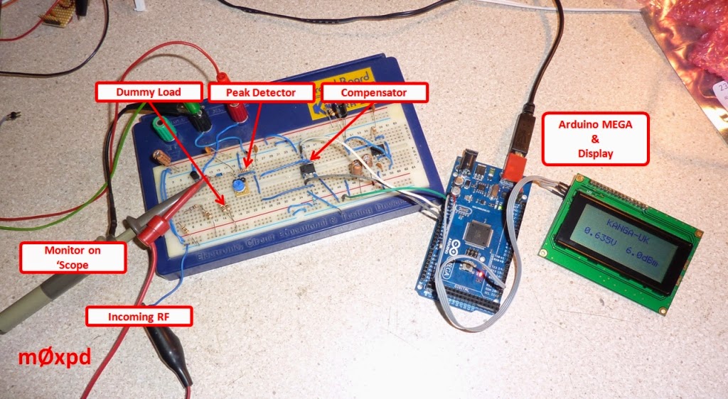
In the current (September) issue, Ed talks about "RF voltage and power measurement" and I drew heavily on his QRP load and compensated peak volt meter, to come up with a system, the important parts of which follow closely Ed's "words and music"...


As you see from the photo at the head of this post, I've hooked up the compensated detector to an Arduino, which makes a voltage measurement (rather than the moving coil meter / current measurement in Eamon's system). The Arduino runs some trivial code, the more important parts of which are reproduced here...


The "LCD_Display_Power()" function displays the measured peak voltage on the LCD (after doing some simple math to convert the number from the Analog to Digital converter to a voltage - and then to convert to dBm [assuming the measured peak voltage to have been associated with a sinusoidal waveform]), resulting in this sort of display...


I observed the response of the new meter as I applied different amplitude RF signals from my old Tektronix SG503, which sits on the shelf ready for little tasks like this...


I monitored the amplitude on a scope and plotted the RF peak voltage (as "eyeballed" from the 'scope) against the new meter's output...


All pretty encouraging for a first shot - there is a nice linear characteristic, indicating correct operation within the "operating range" of the instrument (if I might abuse that grand word). The bottom end of the dynamic range is pretty much where I expected (from a combination of an LTSpice simulation and consideration of the numerical resolution of the ADC), allowing useful measurements down to -6dBm and indication to below -12dBm. The top end of the measurement above ISN'T the top end of the dynamic range of my new meter - it's the top end of the available outputs from the SG503 source, which only goes up to 2V into 50 Ohms.

As you might understand, there are some "other refinements" in my power meter, not described in the "simple telling of the story" above. I'm working on these at the moment and will publish them when the time is right. Notwithstanding these other ideas, the basic architecture above will present a framework for some interesting test equipment - watch this space.

...-.- de m0xpd

Sunday 17 August 2014

Breadboard BITX

Having first built a BITX bidirectional amp as a plug-in module then developed a mild obsession for plug-ins associated with the BITX, I found the temptation to build a complete plug-in BITX radio too much to resist...


It started with some batch production


of the remaining two bidirectional amplifiers...


Then I turned my attention to the second mixer. I used the circuit I published in my article in SPRAT 158 (see page 7), which includes a driver stage appropriate to the use of a digital oscillator.

I was embarrassed to spot an error in the way I’d drawn the secondaries of the transformer in the schematic in SPRAT – corrected below...


Here’s the layout I used on the little piece of Veroboard, which is of the now standard “12 holes” width for this project...


and here’s the little mixer in the flesh...


The only thing missing from a viable receiver was an AF amplifier – so I made up a module based directly on Farhan’s original ‘386 design (seen here with corrected pin-out)...


My vero layout looks pretty relaxed...


but the large junk-box capacitors make it all a bit crowded and ungainly...


Here’s how the whole shooting match fits together – starting with (at top left) one of the g3rjv / G-QRP band-pass filters (another of my standard plug-ins) and then the set of recently described modules associated with the BITX. My legend "BA" signifies Bidirectional Amplifier. I am running a 12 MHz IF; the VFO is derived from a DDS and the BFO is implemented on the VXO seen in the photo...


The system on the bench shows the VFO running the new Kanga VFO 3 code in a new, sloping front desk-top enclosure I’m in the process of building. I haven’t any nice pushbuttons (which will occupy enlarged versions of the pilot holes either side of the tuning knob) in the junk box – hence the temporary pushbuttons on the outside of the enclosure in best Heath Robinson style.


You can see (given my near 12 MHz BFO) that I was listening to the 40m voice band – in fact, I was listening to the Lighthouses On The Air weekend.

I now have a hugely flexible experimental platform, on which I can mess about with some new ideas. I haven't made a driver or PA stage (because I'm not interested in transmitting with this set-up - it has just been made to investigate some receive concepts). But all the functionality is there - this is a complete BI-DIRECTIONAL system, missing only the mic pre-amp, driver and PA. I have those - of course - in my main h/b rig.

An interesting experiment but – most important - it has been fun to build.

...-.- de m0xpd

Sunday 10 August 2014

OCM

It is like those snacks - you know, the ones that come in a cardboard tube - "once you pop, you can't stop". Once you've made one plug-in module, you just have to make another.

Apparently it is called "Obsessive, Compulsive Moduling", OCM for short.

I was still playing with my cheap 'n dirty SSB experiments, using this hideous, mal-formed 8 MHz filter...


I wanted to switch to 12 MHz - and the obsession took hold.

Here's the resulting module -


Once again, it is the now standard 12 holes wide - that way it perfectly straddles the "blocks" on my solder-less breadboard, using up real-estate in the most efficient way possible.

As soon as I had the crystal filter, I needed to be able to put a local oscillator in just the right place to be able to use it in either an upper- or lower-sideband application, so I built a little circuit that would allow me to pull a crystal a few kHz. [Editor's Comment: That's a dumb idea - why doesn't somebody have the good sense to use a DDS in this role?]

I prototyped it straight onto the solder-less breadboard but I soon realised that this would be a useful "standard module" to have as a "keeper".

Once again the OCM took hold and I ended up spiraling out of control into module construction...


As you see, the VXO module has a socket to allow the crystal to be changed and a trimmer capacitor to set the frequency.

Here are the new modules joining the existing ones on the breadboard...


There's even a 5V regulated PSU plug-in already there, providing evidence that my OCM is a long-standing disorder and not some new affectation!

...-.- de m0xpd


Saturday 9 August 2014

Plug-In BITX Modules

Anyone who reads these notes will already know that I like plug in modules for solder-less breadboards. Here's a couple more to add to my fleet...

I've been playing around with some ideas for cheap 'n dirty SSB generation and I needed a broadband amp - so I thought I'd make up one using the bidirectional design from the BITX. I enjoyed making it so much I made a matching mixer with integral driver too...


The amp is one of the standard building blocks from the BITX...


I spent some time figuring out a layout on a scrap of Veroboard - trying to fit it onto a piece 12 holes wide (as that's the best width to work with on my breadboards).

Here's the layout I came up with (seen from the "component" side - the red "x's" indicate breaks in the copper tracks)...

and here's the finished article...


Flushed with the success of that module (and needing a mixer) I made up the second unit, implementing this section of the original BITX design...


Again, I wanted it on a piece of perforated board 12 holes wide, so I kept to the same overall size - here's the layout...


and here's the mixer in vivo...


Needless to say, the little modules work fine (after I'd remembered to make the last break in the copper track on the mixer circuit - my forgetfulness was causing an obscene amount of current to flow and making a 100 Ohm resistor get very warm).

No doubt the big boys will tell you that Veroboard and (in particular) solder-less breadboards aren't the thing for RF work. I don't care - they're really useful for trying out quick ideas and kludging systems together to see if things work.

With the added flexibility that these little ready-made modules bring, playing with RF is - literally - play.

...-.- de m0xpd

Sunday 3 August 2014

Enhancing the Enhanced

I was pleased to use one of the nice new 20 * 4 backlit LCD displays from Kanga in my newly enclosed rig, as reported last week. Having done that, it was only reasonable to re-work the Kanga VFO system to benefit from this new display (the code I produced for the Kanga VFO is at the core of my new rig's software).

Here's the System I was playing with this morning - a stack of Arduino (which happened to be a MEGA), a DDS shield (an early prototype) and a proto shield hosting a rotary encoder and some push buttons. You can see the original 16*4 LCD display and the new 20*4 unit...


I wanted to produce some code that would allow users to run either the 16*4 or the 20*4 display - which required a certain amount of juggling with the display routines. Accordingly, I've added a constant at the top of the program that the user must set to the appropriate value:

lcdWidth = 16;   or   lcdWidth = 20;

according to the display they are using. The same code then compiles to manage the display accordingly.

The somewhat congested display format of the original system is retained if the 16*4 display is chosen...


but things get a little more easy on the eye when the new display is used ...


I'm afraid the new display is REALLY difficult to do justice to in a photograph (at least with the poverty of my equipment and skills). Take it from me - it looks great in real life. Better still - look at one on the Kanga stall at a rally near you - you'll see what I mean!

I also took the opportunity to address a few other issues when I was messing with the code this morning - hopefully this is a genuine enhancement over what already was an enhancement on the original VFO system!

The code is available for download from here .

 Let me know if you have any problems / suggestions - but remember that this is offered as a free demo of what can be done, rather than a finished, polished system. You get what you pay for!

...-.- de m0xpd