My interrupt-driven code for the rotary encoder certainly has made a worthwhile improvement to the "feel" of my rigs - particularly the "Parallel IF" rig. But I've noticed one little wrinkle in the otherwise silky-smooth operation...
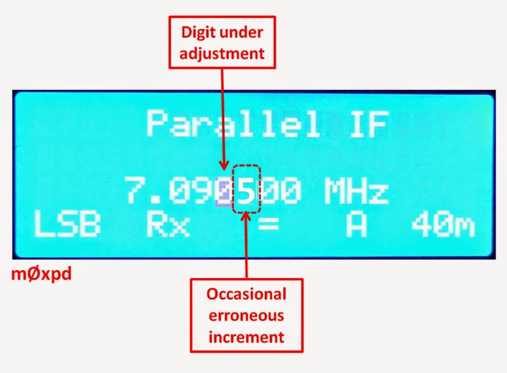
Just occasionally, when adjusting one of the digits, there's an unexpected change to the next lower digit, as shown in this (mocked-up) image.
You see from the block cursor position in the image above that I'm intending the Rotary Encoder should adjust the kiloHertz digit - which it usually does - beautifully. However, just occasionally, there's an irritating jump of 500Hz.
Similarly, if I'm adjusting in 100 Hz steps, there could be a 50 Hz "jump". Etc., etc..
Infuriating!
I traced the issue to the declaration of the variable "Turns" (as described in this post) as a double...
double Turns;
and fixed it simply by declaring it as an integer...
int Turns;
Now there are none of these "half-steps".
This minor niggle has been fixed in the sketches Double_DDS_VFO_0v2.ino and Si5351_VFO_0v2.ino, which can be found at this GitHub repository.
If you've used the code, I recommend that you update by making this simple change.
It really is worthwhile!
...-.- de m0xpd
Wednesday 21 January 2015
Sunday 11 January 2015
Tuning Module
It is time for some beta testing of the new prototype Si5351 board and I need to distribute some to colleagues. To simplify that task, I have prepared some complete "VFO" systems...
As you see, there's the standard LCD display on an I2C interface, the new Si5351 board hosted on an Arduino UNO and a new Tuning Module, with the rotary encoder and the two push-buttons required to drive the input side of the user interface (familiar to anybody who has looked at one of the m0xpd rigs or the Kanga VFOs).
The Tuning Module isn't exactly a new idea - having already seen the light of day in the breadboard BITX - but this seems the easiest way to get a complete system up-and-running (more importantly, a number of identical systems spread across the world).
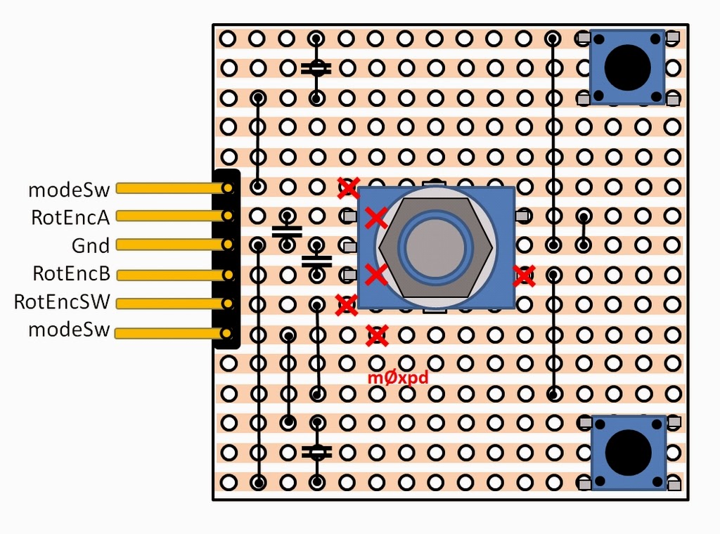
Here - for anybody who would like to do something similar - is the approach I took. I used stripboard, this time with the copper strips facing up, as I could only lay my hands on tactile switches in surface mount format today.
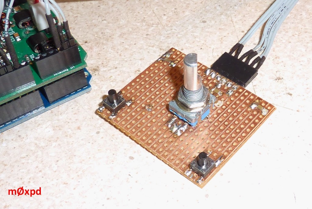
Here's a close-up of one of the tuning modules - I'm too cheap to supply a knob!
I've made the modules in two "editions"; one as shown above with a connector for a cable and one with pins intended for plugging into a solderless breadboard (of course)...
These aren't pretty - they're not supposed to be (as they're just for test purposes). But they show just how little is required to get the complete Parallel IF VFO system up and running.
...-.- de m0xpd
Subscribe to:
Posts (Atom)


