Saturday 5 August 2023

Sample and Hold

 I have had a Sample and Hold for a long time...


It is, as you see above, a homemade module, built around five years ago to the design published by the late, great Ray Wilson of 'Music from Outer Space'. 

I decided - for reasons I'll explain in a moment - that I need a new Sample & Hold. 

There are a number of reasons why you might want a Sample and Hold ('S&H') in a synthesiser, of which the two most common seem to be:

    1) the generation of random sequences by sampling noise (or some other varying signal)

     and

    2) "bitcrushing"

The generation of random sequences is a nice problem, which we'll look at first, by a practical example:


In the oscilloscope screen grab above, you see some random noise, ranging from 0 to 5V (on the channel 3 trace in magenta) and samples of that noise, captured (sampled) at a regular rate and held between these sampling points (seen on the channel 4 trace in light blue). These values constitute a random sequence.

"Bitcrushing" is an audio effect that produces distortion by reducing the resolution or bandwidth of a signal. 

The name might imply that the technique works only by reducing the resolution of amplitude quantisation (i.e. the number of bits used to represent the instantaneous amplitude of the signal). However, as the definition above confirms, the effect actually speaks of the overall bit rate, so sample rate is involved as well. A sample and hold alone can't implement resolution reduction but it certainly can demonstrate sample rate reduction, as we shall now see:


In the oscilloscope screen grabs above, you see a triangular wave, again ranging from 0 to 5V (on the channel 3 traces in magenta) and samples of that triangular wave, captured (sampled) at a regular rate and held between the sampling points (seen on the channel 4 traces in light blue). Various cases are shown, indexed by the yellow integers.

In case 1 the sample rate is so high that you can hardly see discrete 'samples'; channels 3 and 4 pretty much overlay each other.

In case 2, the individual 'samples' are just becoming visible and there is a clear step-wise sequence in channel 4.

By case 3 (where there are approximately 11 samples per period of the triangle), the steps are clearly visible, but there is enough information retained to be confident that the underlying signal is a triangular wave.

By case 4 (where there are now only around 6 samples per period of the triangular wave) the blatant step-wise nature of the signal is such that you have now insufficient information to reconstruct the triangular wave (as opposed - for example - to supposing it to be equally possible that it was a sine-wave of the same frequency). The sampling has lost the early harmonics of the triangle wave.

You could take this further, of course - right up to cases where you start to push Shannon's limit for the fundamental of the triangle wave itself.


In case 5 above, we're still not at the Nyquist rate (we still have around 3 samples per period), but there's nothing of the original signal left, except its fundamental frequency.

The Sample and Hold system certainly has bitcrushed the nice triangular signal of case 1 by the time it gets to case 5, whatever you take bitcrushing to mean!

There's another reason I like using sample and hold devices, different from the two "standard" examples above. It is to extract notes from sequences. To extract -  if you will - a sub-set from a set. 

Here's the example:


In the oscilloscope screen grab above, you see part of a pitch sequence coming from one of my sequencers, (and so ranging between 0 and 5V, seen on the channel 3 trace in magenta) and samples of that signal, captured (sampled) at a regular rate and held between these sampling points (seen on the channel 4 trace in light blue). These channel 4 values are individual 'notes' from the channel 3 pitch sequence, selected at the times the sample and hold is triggered.  In this case, channel 4 is sampling one in four of the 'notes' on channel 3.

I like to use these notes as "pedal notes" or notes for bass voices to play whilst other voices play the faster sequence (in a higher octave). It is an easy way to build harmony.

I have been using my old MFOS S&H module to do this for many years, but was irritated by two of its  "features".

Firstly, it has front panel adjustments which allow you to apply gain and offset to the sampling process. These are controlled by the two knobs closest to the array of sockets (see the photo at the head of this post). To use the device in my "pick a note out of a sequence" application, it is critical that the sample and hold has exactly unit gain and no offset. 

But every time I plugged something it, I couldn't help touch the knobs that displaced both these settings. This meant that every time I used it I had to re-set, costing time and irritation! 

Also - to be honest - my MFOS sample and hold module does suffer a little 'droop' in its hold phase, as charge on the hold capacitor leaks away over time. 

So - my plan was to address these issues in a new unit, with NO FRONT PANEL ADJUSTMENT for gain or offset, and better hold performance.

I started off with a re-spin of Ray's MFOS unit, which uses a C-MOS 4066 analog switch to switch charge onto the hold capacitor. I had a prototype of this new circuit working pretty quickly and quite well enough to "go to production", but my attention was caught by the simplicity of Moritz Klein's S&H. This design, which features both in Moritz' YouTube video and in the Erica Synths ".edu" module, uses a FET to switch charge. I felt I ought to give this approach a whirl too.

As readers already know, I am a big fan of Moritz Klein, having used his VCO core in the SubHarmonics module and identifying his important pedagogy in synth DIY. Moritz is explicit in calling out the limitations of the FET in this application, but he surprised me by saying:

“If you want to sample a tuned sequence for your VCO for example, you’d absolutely need precision,    otherwise it would sound way out of tune. But that’s a very specific and, frankly, not that practical use case, at least from my perspective.”
                (M Klein, Designing a sample and hold circuit from scratch, 16:31) 

So - Moritz thinks that my application is a very specific and not that practical use-case, which would absolutely need precision!

Hearing that, I felt it was OK to give up on the FET (which at that point I had working as well as the analog multiplexer) and look elsewhere. I needed to look no further than Eddy Bergman's site, where a recent post described a sample and hold derived from a design by Rene Schmitz. These used the LF398 device - an application-specific S&H chip.

The LF398 sounded way too expensive for somebody like me -  a cheapskate who had been messing around with CD4066s and J113s. But I took a look on our favourite auction site and found some LF398s for about £1 each. I set one up in the same breadboard I'd been using with the analog switch and the JFET and suddenly everything got a lot easier!

So - a new sample and hold module is born...


You can get all the design information on my github. And you can tell it works, because all the examples I showed above were generated by this new S&H module. 

I need never worry about knocking knobs again!
73
m0xpd


Sunday 18 June 2023

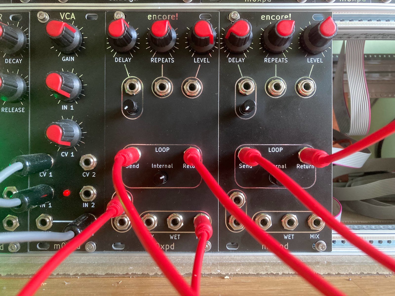
encore!


Some weeks ago I noticed a flurry of discussion of the PT2399 device on various Facebook groups of which I'm a member. The PT2399 is marketed as an 'Echo Processor', offering the ability to generate a delayed version of an audio signal and - thereby - to form the core of a simple echo effect. 

What is most interesting about the device (which is available in a 16-pin DIP) to me and millions of others who dabble in audio all over the world is its price - you can have them for around fifty cents retail if you shop around.

You won't be surprised to hear that  - in consequence of the ridiculous price - there are myriad delay and effects units available based on this device. Some are for guitar and many more are now available for voice applications (type 'PT2399' into ebay and you'll be offered complete 'reverb' systems for less than the price of a pint of beer). The recent discussion I mentioned above was on synth groups - where PT2399's are used for delay/echo applications too.

So - I got me some samples of the PT2399 and started playing with them. 

I liked what I heard to such an extent that I made a new module, pictured above. 

I have called it encore! not in a vulgar outburst of self-congratulation. Rather in a play on the French word, the meanings of which include 'more, again,' etc.. Appropriate, I think, to the repetition central to 'echo'.

My module is rather different to the simple 'reverb' systems you can buy on ebay (I hope). 

For a start, I've added additional low-pass filtering to the input (2nd order) and to the output (4th order) of the system to restrict the bandwidth and thereby hide some of the noise inherent to the 1-bit processing used in the PT2399 (which drops in sample rate to achieve the longer delays). 

Here's bench work on measurement of the frequency response of the prototype's output filter, which has a pair of Sallen-Key stages in as close to Butterworth configuration as E12 components allow without getting too precious about tweaking.


As it happens, a shortage of any spare op-amps on the PCB meant I ended up neglecting to put buffering between the output of the PT2399 (and it's associated passive network, which does not have a particularly low source impedance) and the input of this filter stage (which similarly doesn't have a particularly high input impedance). So there will be some inevitable interaction, which means we won't get the measured flat(-ish) passband and -24dB/8ve from 8kHz seen on the analyser screen in the photo above. Doesn't matter - it's only for a synthesiser! 

Aside from filters, encore! has some much more interesting additions, specific to synthesiser application.

All the main parameters (delay, gain of the recursion loop [controlling the number of repeats of the delayed signal] and level of the echo signal) are voltage controlled. This is achieved by voltage controlled amplifiers (in the case of the repeats and the level) and by a voltage controlled resistor (in the case of the delay). These features rest heavily on the shoulders of the late Ray Wilson of Music From Outer Space, who designed a couple of pt2399 echo devices. I modified Ray's voltage control circuits for use in this module.

Also, I have provided support to allow users to add external elements to the recursion path which feeds the delayed audio back into the input of the system via a 'send / return loop':


This allows (e.g.) a filter to generate frequency selective echos or a second delay unit to create more complex echo structures.


Details of the design (which has been published under a Creative Commons CC BY-SA 4.0 License), including schematics and full PCB details, are available in a github repository.

It's amazing how an inexpensive device, made more inexpensive by high demand, can generate opportunity for such pleasure.

73

m0xpd


Sunday 28 May 2023

Bombing Run

I was sitting here at my computer yesterday, quietly building envelopes from a bunch of straight-line segments (no, I can't tell you why). 

Suddenly, the quiet was broken by a familiar and evocative sound - the rising rumble of a group of beating piston aero engines. 

The rumble rose to a dramatic, unmistakable roar and sure enough - as I looked out of my window - Avro Lancaster PA474 of the Battle of Britain Memorial Flight thundered over my house at 12:26 on a heading of 170 degrees at 825ft (according to the flight track I just retrieved from RadarBox).


Interestingly, the same track that gave me her altitude placed her a good deal E. of me (some 200m), but I (and the XYL, who saw her independently from the garden) have PA474 much closer on track for a 'direct hit' than that.

The Lancaster was flanked by a Hurricane and a Spitfire and the Hurricane (which was flying off the Starboard wing, which seems typical of all the images you see of this BBMF formation) was certainly well W. of my location. 

The formation was travelling between 'appearances' at Bury and Smallwood to place themselves over my QTH and after their performance yesterday they returned to overnight at Liverpool Speke to continue their part in the Battle of the Atlantic Memorial events.

The Lancaster will be showing her bomb bay to the good folks at Bury again today before going on to Stockport and then back home to Lincolnshire. If she runs a straight line over the ground between Bury and Stockport that will take her well E. of me but if (as happened yesterday) she routes via Barton field, I may get to see her again this lunchtime.  As I write we do have cloud cover, but it isn't nearly as low as it was for Charley's big day, which stopped PA474 flying down The Mall.

Last time I saw her, as recorded in these ramblings, was at Bletchley Park, from where we also saw another BBMF Spitfire on a subsequent visit.

So - fingers crossed I see the Lanc again today. Unfortunately, she's going solo today (so only 4 Merlins!) as the Spitfire and Hurricane are strutting their stuff elsewhere. I think I'll maximise my chances of a sighting by standing atop the local 'hill' (such as it is), rather than skulking indoors.

Many thanks to the good folks at the BBMF (and similar) for keeping these wonderful machines flying (notwithstanding their bloodstained past) and honouring all those who served and serve. A wonderful sight and an even more wonderful sound.

73   
m0xpd

Update:

I did see her again today, and she did route via Barton, but then turned hard for Stockport, taking her well East of me. Here she is at 1025 feet, approx. 4km away over the M60, Junction 7, en route to Stockport:


Saturday 6 May 2023

SubHarmonics

A couple of posts ago I wrote "I'll have something to say about adding and 'mixing' harmonics; watch this space." 

Well, the time has come - enter my new module, SubHarmonics


Before I go any further, I ought to explain what sub-harmonics are and why I might waste time and money developing some electronics which generates and manipulates them.

You will have heard of 'harmonics'; the idea that any periodic signal is composed of (a d.c. component plus) a sum of terms having frequencies at integer multiples of the 'fundamental frequency', where the fundamental frequency is the reciprocal of the period. 

This concept, which is the core of Fourier analysis, underpins some of the most important mathematical and computational constructs of our age, including the Fast Fourier Transform. It also explains the "Harmonic series" of musical notes:  those notes some of which can be sounded on a natural trumpet (/bugle) or trombone (excepting 'pedal notes'), a string, etc.

It is possible to construct another series of frequencies starting on a fundamental which, instead of having members whose frequencies are integer multiples of the fundamental frequency (f0, 2f0, 3f0, 4f0, ...), has members whose frequencies are integer quotients of the fundamental (f0, f0/2, f0/3, f0/4 ...). This is called the undertone series or sub-harmonic series.

Why does the sub-harmonic series matter musically? 

Well, one of my sons-in-law plays bass and (as if his bass isn't low enough already) he likes to add an "octave down" effect 

to add sound an octave lower - a sub-harmonic. So, sub-harmonics can add bass - but they are not just used to add weight and "depth". 

Since two different sub-harmonics of a common fundamental are harmonically related they can be combined to represent harmony - this is the main reason for my interest

Two distinct sub-harmonics occur at a frequency ratio of m/n where m and n are small integers. This "ratio of small integers" is the "recipe" for a musical interval (an octave is 2/1, a fifth is 3/2, a fourth is 4/3, etc) - making the combination of two sub-harmonics (often - but not always) musically useful. 

That's the background - now back to the electronics:

My module "SubHarmonics" takes a fundamental signal, 'X', which is either generated by the module's internal Voltage Controlled Oscillator or derived from an external signal applied to the "Ext X In" clock input, and generates two square-wave signals, 'A' and 'B'. 

These signals A and B are sub-harmonics of X (that is to say, their frequency is a quotient resulting from dividing the frequency of X by an integer divisor) and each divisor is set either by a front panel control on "SubHarmonics" or by a Control Voltage applied to the relevant control input. 

You can see the divisor controls, CV inputs and indicators on the front panel:


The divisors can be set between 2 and 18, giving the unit a range a little over four octaves.

The two sub-harmonics are available individually as outputs and they are also applied to two internal modulators which combine A and B through switching equivalents of 'amplitude modulation' and 'ring modulation'. The result of these two modulators is passed to a voltage-controlled crossfader circuit to produce the module's fourth output: a "modulation mix". 

The signal on this "modulation mix" output can be either of the two modulation types or a mix of the two.

The 'scope screenshots below show the module in action. There is an example of the 'ring modulation', implemented by an XOR operation between A and B (when the Mix control is at minimum, 0V level), left, and the 'amplitude modulation', implemented by an OR operation between A and B (when the Mix control is at maximum, 5V level), right. 

I explained (at very tedious length) how and why modulation by OR gates produces an output identical (in terms of magnitude Fourier Transform) to modulation by AND gates for the particular case of "antipalindromic" inputs in an earlier post; these A and B sub-harmonics are antipalindromic.


The fundamental, X is the top trace in yellow - it is at approximately 600Hz. The first sub-harmonic, A, is the second trace, in Cyan. It is associated with the divisor m := fx/fA = 6 (giving the sub-harmonic at 100Hz). The second sub-harmonic is the third trace, in Magenta. It is associated with the divisor n := fx/fA = 12 (giving the sub-harmonic at 50Hz). The X, A and B traces are the same in the plots above.

However, changing the Mix setting changes the fourth trace, the Mod Mix output shown in Blue. It will be noted that the Mod Mix output is actually inverted; it goes from 0V to a negative value (I had no spare op-amp stages to correct this and no more space on an already busy board!) 

In the left hand scope screen above, the Blue trace can be seen to describe the inverted exclusive OR on A, B. In the right hand scope screen above, the Blue trace describes the inverted XOR on A,B. 

This inversion is performed in analog (by the action of the cross-fader), but it is (in this case) working as a perfect logical complement (making inverted OR look like NOR etc).  Things are more complicated when the Mix control is at an intermediate setting:


Here, (above) with the X, A and B signals as before, the Mod Mix output (bottom, Blue trace) is seen to have a more complex waveform, mixing together elements of the balanced and unbalanced modulated signals from the two extreme cases illustrated above; the crossfader works!

In use, setting the 'Mix' control at the lowest setting gives the clean 'ring modulated' sound and increasing the 'Mix' setting increases the complexity of the sound toward the richness (/harshness) of the simple product of A and B.

The beauty of "SubHarmonics" is the ease with which a single pitch signal can generate a tone (or a 'melody') and the module can then fill out this single line with not just two sub-harmonics, but with a rich, inter-modulated texture. 

Everything about the module is dynamic, being controllable by external control voltages, which can come from sequencers, LFOs or random generators, to give an infinite variety of expression.

The system is implemented largely in CMOS logic on two PCBs. The internal VCO uses the core of Moritz Klein's 'Shapes VCO',  (later used as the Erica Synths mki x es.edu VCO), which fits nicely with the CMOS environment and is a very stable, elegant design - like all Moritz's work. The crossfader uses half an LM13700 OTA and the controls and CV inputs for the divisors are read and decoded by a PIC 16F676.


I have posted complete design files for the PCBs and Front Panel and code for the PIC in a GitHub repository.

It has been great fun developing this bird's nest of wire on the bench


 into the finished "SubHarmonics" module - 


but it is even more fun using it.

73
m0xpd


Monday 24 April 2023

EAGLE Toroid Library is Available (again)

Yesterday, after a request from Giannis in SV-land, I uploaded my EAGLE Library for inductors and transformers wound on FT37 and FT50 Toroidal Ferrite Cores to a github repository.

I had published this library many moons ago to the CADSoft EAGLE Library page, but it no longer appears on the Autodesk EAGLE Library collection. Perhaps it got lost during the transfer of ownership of EAGLE or perhaps they just don't like my little library 😃

Whatever the reason, it is now online again and available for anybody to use.

The library was originally created and used in several of my projects, including the Tx and Si5351 shields and has been successfully used by a number of others who have reason to play with these fundamental building blocks of practical RF circuits. 

However, you should be careful before you use it. I have been burned by libraries from trusted sources and I would advise caution; you should check that it works in your application. Whilst it is offered in good faith, it comes with no warranties that it is suitable for any purpose!

Let me know if you have success with it,

73 de m0xpd

Thursday 13 April 2023

VCAs and Old Dutch Masters

 There's a saying out there, which is almost a truism:

    "you can never have too many VCAs".

Having some time on my hands today, I decided to knock up another of my takes on Yves Usson's 'simple VCA' circuit, which I have cast into Eurorack format. I made the VCA in an hour or so, with music ringing in my ears.

You can see the result in the pictures below, which show the front and back of the finished module as well as the PCB from the side which usually is obscured by the front panel.

My implementation pretty much follows Yves' words and music, only I drive each of the two outputs  actively in order to use the last of the four op-amps in the quad package you see above. 

Yves' circuit used a twin and a single op-amp and that's not very space efficient when you're squeezing chips onto a little board for Eurorack. I couldn't bear to see the last stage of my quad package sitting there doing nothing!

This is the fourth of these units I've made now (one is DC coupled, with linear controls, to use with CV signals) and they work like a charm. With the 4 other simpler CA3080-based VCAs already in my system (which were based on a MFOS design), I may not have too many, but I'm getting by for now.

As I said, I was building today "with music ringing in my ears". I wasn't listening to music - it was the memory of last evening, when I went to a wonderful gig at The Met, Bury, to hear Dutch "prog-rock" (and - I would say - "fusion") legends, FOCUS, who are on their 50th anniversary tour. I have been a fan since the 1973 UK release of "Moving Waves", so it's been 50 years for me too.

The band (who I've seen many times before) were superlative and the drummer, Pierre van der Linden, who played on that original album, was ON FIRE!


I was standing about six feet from another founder member, Thijs van Leer. Let's be clear - there was nothing synthetic last night - just real instruments. But the tonebars on Thijs' Hammond are often held up as an example of additive synthesis.


Talking about tonebars, when the good people at JLCPCB are finished with the pcb designs I sent them yesterday, I'll have something to say about adding and 'mixing' harmonics; watch this space.

I'm off to play with my new VCA and to revel in more music from "the most successful and the most appreciated of all the Dutch pop-rock exports" - and my favourite band of all time.

73
m0xpd


UPDATE (15/04/23) :

Design files for my Eurorack version of the YuSynth VCA 


have now been published on my github.


Tuesday 28 March 2023

Logic Gates and a Modulation Curiosity

Recently I added some logic gates to my synthesiser. Not the familiar little chips we know and love

rather, logic gates especially for musical application.

I’ve had an OR gate in my synth from the early days, finding it useful for combining trigger signals from my sequencer to build up drum patterns, etc. Originally, I used the simplest diode-based OR gate designs, such as that as seen on the Doepfer DIY page. Subsequently, I augmented this with a level converter, to allow the OR gate to trigger those modules requiring high voltage signals (I still have some old MFOS modules expecting 10V) even when the sources were putting out timid 5V pulses from a microcontroller. I exploited the same old level converter circuit I’ve used and abused many times before

This original OR gate worked but wasn’t everything I wanted, so I started to toy with a new design and realised it was easy to conceive of an AND sibling for my new OR gate, as they shared many common features.   


My new 4HP logic gates, some of which are seen above, have inputs which are normalled such that you can use fewer than the four available, as occasion demands. 

The modules use the ‘comparator’ structure familiar from the input stage of Ken Stone’s ‘quad logic gate’, in which any input exceeding a voltage of approximately 2 volts is associated with the logic value ‘true’ and voltages lower than this threshold are associated with the complement ‘false’. Thereafter the logic operators AND and OR in my design are implemented using diodes. The output stage is a conventional complementary BJT driver, outputting a signal of 0V (‘false’) or approx. 10V (‘true’), such that the modules also operate as gate level converters when there is only one input.  

Needless to say, they work; the OR gate combines gate and trigger signals as expected and the AND gate gives me new opportunities to create rhythms (e.g. by putting a quaver trigger sequence into one input and putting random or asynchronous periodic signals into the other inputs, to generate a complex or random pattern of onsets on the quaver beats). However, let’s present some evidence before we go any further. 

Here’s a screenshot of the ‘scope showing two square waves going into inputs of one of my AND gates.


New AND Module operating on two square waves at 2:1 frequency ratio

The top two traces are the inputs and the bottom trace is the output. The square wave signals are coming from two of my CEM 3340 oscillators and (as seen above) they are tuned an octave apart (i.e. a 2:1 frequency ratio apart). The fundamental frequency was a little over 50Hz (by chance). These 3340 oscillators (which are based on the Digisound 80 VCO design) usefully produce a pulse output which is at 0V and 10V). The output is seen to successfully implement the AND of the two inputs. 

To be honest, it was difficult to tune the oscillators to achieve the image above. Getting the 2:1 frequency ratio was easy enough; I could do it by ear and I could back it up by locking the oscillators using their sync capability. BUT, setting the PWM to get a 50% duty cycle on both signals was not nearly so easy. More of this later…

For convenience in grabbing images (particularly as I haven't got round to hooking up the scope to my computer, which is now a MacBook - Rigol's offering is for Windoze) I decided to connect the arrangement to a simple Chinese ‘logic analyser’, which has an HC245 input (capable only of handling 6V). As the signals already were overtopping this 6V limit, I had to make some limiters before I could hook up the logic analyser, but these were just a series resistor and a diode (to 5V) per channel, so it was no great shake. 

Here's the toy logic analyser and the limiters on the bench:


Here is a screenshot from the USB interface (using Sigrok’s ‘PulseView’ software) of the same AND function as that seen on the ‘scope screen (captured at the same time, but without the hassle of photography):

Figure 1     AND of Square Waves recorded in PulseView, Ta=4, Tb=2 


Now we can turn our attention to the new OR gate, fed by the same square waves. This produced the expected image on PulseView:

Figure 2     OR of Square Waves recorded in PulseView, Ta=4, Tb=2 

Having tried all the obvious and familiar things with my new logic gates (like OR-ing drum triggers together and generating interesting patterns with the new opportunities presented by my AND gate), I couldn’t resist sticking some audio frequency signals through them and listening to modulation effects. It produced some surprises…

Some observations on modulation

Just as in the demonstrations reported above, I put square waves into two inputs of the OR and AND gates, but at somewhat higher frequencies. I then listened to the resulting output signals. 

I knew what to expect for the AND gate (because the AND function is a switching operation, closely related to multiplication, as we’ll see), but I had less of an intuition for the OR gate. 

I wasn’t too surprised to find that the outputs of the OR and AND gates sounded different when fed by the same pair of square waves, but I decided to do some poking around with some simple maths to explore what was going on – then the surprises really started. 

I ended up falling down a terribly deep rabbit hole, where strange symmetries inherent in musical intervals could make AND gates behave like OR gates, especially when seen "through the looking glass", whose reflections mirror and reverse words and images.   

All the stranger, since these logical entities had fascinated one Charles Lutwidge Dodgson, who was born and grew up in Daresbury (where I worked for the greater part of the last 20 years), wrote an interesting little book on logic, took suspicious interest in pre-pubescent girls, and became world famous for writing books about falling down holes into wonderland.

To help me navigate my own wonderland, I wrote a simple piece of code in Octave.


Octave is a Scientific Programming Language which is effectively an open-source equivalent of MATLAB. I’ve lived my professional life depending on MATLAB and the idea of life without it (now I’m retired) is slightly depressing, made bearable by the presence of Octave. In its latest form (I’m running 8.1.0 on my MacBook) – with additional packages to do all the important things like signal processing (which I’ve been exploiting in what follows) - I can get by without the even more depressing prospect of shelling out £105 per year for a home license for MATLAB (plus £29 for packages). I can’t claim poverty, but I can confirm that my reputation as a cheapskate is showing no signs of wearing off.

Here is the core of the code I’ve been using to look at the effects of two square waves being thrown at various kinds of ‘logical’ modulators:

% Specify the Periods of the two squarewaves:
Ta=10;
Tb=12;
% Specify the duty cycles of the two squarewaves:
DUTYa=50;
DUTYb=50;
% Calculate the normalised frequencies of the two squarewaves:
fa=1/Ta-eps;
fb=1/Tb-eps;
% Generate a time vector:
tmax=1000;
t=[0:tmax];
% build the squarewaves:
a=(square(fa*2*pi*t,DUTYa)+1)/2;
b=(square(fb*2*pi*t,DUTYb)+1)/2;
% apply the logic:
c=and(a,b);
d=or(a,b);
e=xor(a,b);
% Now look at the result in the Frequency Domain:
% build a window:
w=window(@blackman,length(a)).';
% and calculate the FTs
A=fft(w.*a);
B=fft(w.*b);
C=fft(w.*c);
D=fft(w.*d);
E=fft(w.*e);

You will see that I’ve set up a system to play with two rectangular waves, ‘a’ and ‘b’, which are the inputs to logic operators, interpreted as modulators. The modulators produce the signal 'c'  (which is the result of passing 'a' and 'b ' through the AND operation). Similarly, variable 'd' is the output of the OR operation and 'e' is the result of XOR. The waves ‘a’ and ‘b’ are easily related in period (/frequency) by the ratio of small integers (through the variables ‘Ta’ and ‘Tb’, although non-integer values can be entered here) and the duty cycle of the waves can also be directly controlled (through variables ‘DUTYa’ and ‘DUTYb’); the waves become truly 'square' when DUTYx=50. The code also windows the time-domain signals and computes Fourier Transforms.

Here's an example of running that code, seen first by looking at time-domain results.
Figure 3: Square Waves a, b, (Ta = 8, Tb = 10) modulated by AND and OR gates

The traces above in Fig 3 show 1000 samples of the two square waves 'a' and 'b' and the consequences of applying them to two logic gate modulators. The first is the AND gate (indicated by the expression ‘a^b’, where ∧ denotes logical conjunction, the operation for which ‘AND’ is the operator). The second is the OR gate (indicated by the expression 'a∨b', where ∨ denotes logical disjunction, the operation for which OR is the operator). These are models of passing the two signals, ‘a’ and ‘b’ through my new AND and OR gates.

Also seen (in red) in Figure 3 is the consequence of applying a (Blackman) window to the input and output signals. We need these windowed signals, because next we’re going to look at the signals in the Frequency Domain and we want to avoid smearing the energy to frequencies where it doesn’t really belong.

Here’s the same data in the frequency domain:
Figure 4: Magnitude Spectra of Square Waves a, b, (Ta = 8, Tb = 10) 
modulated by AND and OR gates

Figure 4 represents the same signals seen in Figure 3 (the uppercase variable names denote frequency-domain versions of the lowercase time domain entities). The plots within Figure 4 are parts of the magnitude Fourier Transforms of the time sequences in Figure 3, plotted on a log (dB) scale against normalised frequency, fn, (running from fn = 0 to the Nyquist Frequency, fn = 0.5).

This is, in many ways, expected; modulating the two signals should generate a new sequence having a fundamental at the difference frequency between the fundamentals of A and B – which it does. But it is also unexpected.

This is the result I saw when I first ran this code and in one particular way it is STAGGERING. It appears to say that the (magnitude) spectrum of the output of the AND gate and the OR gate, when fed by the square waves as described, should be identical. 

Let’s just check that by over-laying the bottom two traces on an enlarged single plot, just to be sure…

Figure 5: Comparison of the Magnitude Spectra of the outputs of the AND and OR gates
when fed by Square Waves  a, b, (Ta = 8, Tb = 10) 

Yes – identical except for one place – zero frequency, fn = 0 (d.c. as electrical engineers call it).

This is crazy – when I listened to the output of my AND and OR gates, they certainly didn’t sound the same.

So I went back to the synth and made sure they were tuned this way (Tb = 1.25Ta). They were – but the outputs of the two gates STILL didn’t sound the same. Then I decided to check the only thing that could be different – the duty cycles.

I found that the duty wasn’t exactly 50% when the PWM control on my oscillators was centralized.


So I set the duty cycle of both pulse outputs as best I could to 50% and – yes – the sound of the OR and AND gate modulating the same pair of square waves suddenly sounded similar – just as the code predicted. The outputs of the AND and the OR modulators sounded the same!!

I went back to the code and checked the sensitivity of the system to the ‘DUTYx’ variables. Sure enough, when the DUTY of either or both square waves changes, the spectra of the outputs of the AND and OR modulators diverge. 

Here’s the overlay of the two spectra when DUTYa = DUTYb = 40%

Figure 6: Comparison of the Magnitude Spectra of the outputs of the AND and OR gates
when fed by Rectangular Waves  a, b, (Ta = 8, Tb = 10,  DUTYa = DUTYb = 40) 

Hopefully Figure 6 shows up well enough to allow you to see there are several spectral peaks with more than 4dB difference between the spectra of the two sequences – easily enough to make them sound significantly different. 

Let’s summarise here – 
* the result of modulating two rectangular signals by an AND gate sounds different to the result of modulating the same pair of rectangular signals by an OR gate (no surprise) but 
* there are special circumstances (in the case of SQUARE waves with truly 50% duty cycle), where modulation by AND and OR produces the same magnitude spectrum (apart from the d.c. term).

This remains of surprise and interest and is worthy of more comment and consideration. 

In order to understand the significance of the ‘equal magnitude spectra’ observed above, we might ask: What does it mean when two periodic signals have the same magnitude spectrum?

Well, for signals generated by a physical process (as opposed to something contrived), it is likely that: 
one signal is a delayed (time-shifted) version of the other and/or (1.1)
a time-reversed version of the other                 (1.2)

[because these (1.1 and 1.2) will only change the phase component of the spectral peaks associated with the harmonics of the periodic signal – not their magnitude, and will not change the peak at d.c (fn = 0)]
 
Then, inspired by what we’ve seen of the case of the outputs of the AND and OR modulators (whose output magnitude spectra in special circumstances differed only at d.c.), we might further ask: 

What does it mean when two periodic signals have magnitude spectra which differ only in their d.c. component?

This might mean that one of the signals has:
been shifted in mean value and/or                                                    (2.1)
has suffered negation (multiplication by -1) relative to the other    (2.2)

[because these (2.1 and 2.2) will impact the peak at d.c. (  fn = 0 ) but not the other harmonic peaks, which are agnostic to mean value and phase/polarity]
 
With these ideas in mind, I looked at the time-domain outputs of the AND and OR gates, in the special circumstances of 50% duty and relative tuning which permit the output spectra to match other than at d.c. I realised that this could mean that the outputs of the modulators are time shifted and / or time reversed complements of each other. 

Sure enough, under the conditions illustrated in earlier Figures (3,4,5), the time-domain outputs of the two modulators are matched, albeit shifted in time and/or time reversed, if one of them is complemented:

Figure 7: Comparison of the AND and (negated) OR gates' outputs
when fed by Square Waves  a, b, (Ta = 8, Tb = 10) 

Figure 7 shows the output of the AND gate modulator (as shown before in Figure 3, but somewhat enlarged and seen over a shorter duration to allow the pattern to be more clearly seen) and the complement of the output of the OR gate modulator (indicated by the expression ‘¬ ( a ∨ b ) ‘, where ¬ denotes logical negation, the operation for which ‘NOT’ is the operator). The two sequences are compellingly similar – the lower trace appears to match the upper trace but to be shifted to the right (delayed in time).

Note that I said the “two traces are compellingly similar”, not “two traces are identical”. In fact, close examination reveals that the bit sequences from the modulators are time-reversed, making it harder to understand the relationship from the graphic alone (I had to look at the actual bits). 

In fact, possibilities (1.1, 1.2 and 2.2) suggested above in answer to my own questions are at play in this example. The (magnitude) spectral match between the outputs of the AND and OR modulators show that the outputs are are related to each other by time reversal, shift in mean value and negation. In the special conditions defined, their outputs are bit-exact, time reversed, complements of each other. Amazing.  

[It also might appear that there's some time-shift involved too, but - as I'll show below - time shift isn't involved. In fact, there's no memory/filtering/delay mechanism in the modulator capable of imposing a time shift; it's all in the signals - but we're getting ahead of ourselves.]

There are (of course) other combinations of (relative) tunings Ta, Tb, where this condition is met, such as [Ta=10, Tb=10], [Ta=10, Tb=12], [Ta=10, Tb=14], [Ta=10,Tb=18], [Ta=9, Tb=9], [Ta=9, Tb=18] etc. These are recognised as conditions where Ta/Tb is the ratio of two small integers, familiar from the mathematics of musical harmony. Equally, and perhaps more excitingly, there are infinitely more conditions where these conditions don’t hold – or where they don’t quite hold. For, where they don’t quite hold, there are some fascinating possibilities for pattern generation. That's for another day. For now, I must limit myself to...  


Explaining the Curiosity


I had hoped to find an explanation of the mechanism behind this curious convergence between the outputs of the AND and OR modulators in the frequency domain, perhaps by defining those conditions which cause the spectra of the outputs to diverge. In truth, it would have been difficult to find more than simple examples, close to low integer values of Ta and Tb. A general explanation would have involved treacherous summation over too many harmonics! 

I knew there had to be another route to a general explanation, closer to a proof and – after a few days head scratching with this issue on my brain's 'back burner' – I realised what it was. 

In certain special circumstances, the periodic digital signals applied to the AND or OR gate modulator possess a certain kind of symmetry. 

Readers will be familiar with palindromes; words which read the same backwards and forwards (like 'pop', ‘kayak’, ‘radar’, etc.). Well, there are palindromic numbers as well, like 24742, 141 and the binary number 101. Note that these numbers are “mirrored” around their centre; the first and last digit is equal, etc, rather like 'even functions' are symmetric about their centre/origin.  Note that we might also extend the idea from numbers ('101') to sequences (1, 0, 1).

There have also been defined a family of “antipalindromic” numbers, which are the class of numbers having two or more digits and where the symmetry is different (more like an ‘odd’ function). It is easiest to understand in binary, where the antipalindromic numbers are such that the bits in a number are mirrored around the centre by being Boolean complements of each other. For example, the binary numbers 10, 1100, and 10101010 are all antipalindromes.

If BOTH the inputs to our AND and OR gates are antipalindromes over the period of the output of modulator, which is to say, over a period of T0, where:

                                                    T0=(Ta . Tb)/abs(Tb-Ta)  

then that is sufficient to ensure that the outputs of the gates will be time reversed complements of each other. 

Update [3 May 2023]

The equation above is wrong (or, if I'm being kind to myself, incomplete), in that it doesn't correctly describe the singular (and important) case when Ta = Tb. 

What we should say is :

T0=(Ta.Tb)/abs(Tb-Ta) when Tb ≠ Ta      T0 = Ta when Tb = Ta          

To illustrate this to you, let me start by looking at the example we’re familiar with from above, from Figs 3, 4, & 5 (Ta = 8, Tb = 10, Tb = 1.25Ta).

In this case, the period T0 = 40 samples (from the equation above) and one period of the inputs a and b, along with their time-reversed copies (obtained in Octave / MATLAB by the function flip() ), are shown in Figure 8 below.

Figure 8: Inputs and flipped inputs to the AND and negated OR gates
when fed by Square Waves  a, b, (Ta = 8, Tb = 10), demonstrating antipalindromic property 

You can see in Figure 8 that the square wave input (blue trace) is always the complement of its time-reversed self (the red trace) for both input a and input b. The antipalindromic condition is met for both input ‘a’ and ‘b’.

Let’s now look at an adjacent integer tuning (Ta = 8, Tb = 9, Tb = 1.125Ta). In this case the period of the multiplexer output has extended to 72 and comparison of the input square waves and their time-reversed copies over this period reveals that input b is no longer antipalindromic:

Figure 9: Inputs (and 'flipped' inputs) to the AND and negated OR gates
when fed by Square Waves  a, b, (Ta = 8, Tb = 9), input b is NOT antipalindromic 


Since both inputs are not antipalindromic in the case reported in Figure 9, the outputs of the AND and OR gate modulators now sound quite dissimilar, and the negated output of the OR gate no longer follows the same pattern as the output of the AND gate (in fact, if interpreted as a rhythm, it has more onsets in the period – a higher ‘density’ - as seen in Figure 10): 

Figure 10: Output of the AND and (negated) output of the OR gate
when fed by Square Waves  a, b, (Ta = 8, Tb = 9) 


So – I’ve presented a test for cases where two binary input sequences will cause an AND gate and an OR gate to produce complementary, time reversed outputs: ONLY if those input sequences are antipalindromic over the period of the modulator output. I ought to explain WHY a test for antipalindromes is appropriate in this context and explain the mechanism underneath it all.

In order to explain what is going on, we have to call on one of Charles L Dodgson’s approximate contemporaries, another nineteenth century British Mathematician and Logician who became Professor of Mathematics at (what is now) UCL. This man, who gloried in the given name Augustus, formulated a pair of laws important to searching and fundamental to the simplification of logic networks. The laws honour his family name: ‘De Morgan’s Laws’ and used to be a mainstay of undergraduate digital courses in electronic engineering programs everywhere, along with Karnaugh maps, ‘minterms’, Sum-of-Product solutions and all the rest. I used to teach this stuff back in the 1980s.

De Morgan’s laws can be expressed (in the stuffy language which might have appealed to nineteenth century logicians) as:

"The negation of a disjunction is the conjunction of the negations"
"The negation of a conjunction is the disjunction of the negations"    

Let’s see this expressed in a more accessible language, using the symbols of the logic gates which implement the AND and OR operation and Boolean algebra:


De Morgan’s Laws teach us that when we feed an AND gate with the complement of a pair of signals it is equivalent to an OR gate (and versa vice, as Alice might see in the mirror); the only difference is a negation.

This is exactly what is happening with our AND and OR gate modulators; the input sequences carry the complement within themselves. When they are antipalindromes, inputs ‘a’ and ‘b’ are at once themselves and complements of themselves in time-reversed order. They are like a word that reads ‘yes’ forwards and ‘no’ backwards (I’m still trying to find an example – please leave one in the comments if you have one!)  

Let me show you this working in the second simplest example I can conceive of (I would show you the simplest example but it's too trivial, so I’ll leave that to you).

The "second simplest case" occurs when Ta=4 and Tb=2, giving Tb = 0.5*Ta (a 2:1 frequency ratio, called an ‘octave’ in music). In this ‘tuning’, the AND and OR switching modulators generate output sequences with a period of T0 = 4, over which the finite segments of the square wave signals ‘a’ and ‘b’ follow the form seen in Figure 10 below:

Figure 10: Inputs and flipped inputs to the AND and OR gates
when fed by Square Waves  a, b, (Ta = 4, Tb = 2), demonstrating antipalindromic property 


You will see that both these sequences are antipalindromic. Perhaps you recognise that we’ve already played with this pair of sequences before and – indeed – applied them to AND and OR gates.

Recalling how this pair of sequences excited the AND gate (Figure 1):

and the OR gate (Figure 2):

we are now equipped, with an appreciation of the role of antipalindromic sequences and De Morgan’s Laws, to understand why the outputs are (time reversed) complements of each other.

So – unison (Ta = Tb = 2) was too trivial to show you, we’ve seen that the octave (Ta = 2, Tb = 4) works, we’ve seen that the major third (Ta = 8, Tb = 10) works – what about other intervals? 

Well, the fifth (Ta = 8, Tb = 12), the fourth (Ta = 10, Tb = 14) and the minor third (Ta = 10, Tb = 12) work too. It seems this antipalindromic condition is met when square waves of all significant musical intervals are applied to a switching modulator. It is no mere ‘accident’, it is an inheritance of the ‘ratio of small integers’ that lies at the heart of harmony, of rhythm and of music itself.

One last diversion before we clamber out of the rabbit hole; square waves are not the only kind of antipalindromic signal we could feed into our modulators. Let’s check our emerging theory about the generation of spectrally equivalent and time-reversed, complementary outputs from AND and OR modulators by contriving another input.

Here’s an arbitrary antipalindromic binary sequence, 8 bits long,

[1, 0, 1, 1, 0, 0, 1, 0]

repeats of which I can stitch together into a signal of arbitrary length. If I combine that with another signal (for simplicity, we’ll use a square wave at Tb=10 as the second signal, b) the combination of the 8 element length of the sequence above and the period Tb yield a fundamental period for the modulator output of T0 = 40.

Here are the input sequences in this new experiment – made of five repeats of the 8 bit sequence above, the other being four cycles of a square wave.
Figure 11: Inputs and flipped inputs to the AND and OR gates
when fed by a repeated sequence [1, 0, 1, 1, 0, 0, 1, 0], a, and a Square Wave, b, (Tb = 2)


These sequences both are antipalindromic over T0 and so – no surprises – the modulator outputs are spectrally identical (except at fn = 0):

Figure 12: Comparison of the Magnitude Spectra of the outputs of the AND and OR gates
when fed by a repeated sequence [1, 0, 1, 1, 0, 0, 1, 0], a, and a Square Wave, b, (Tb = 2) 


and the outputs are bit-exact, time-reversed complements of each other:

Figure 13: Output of the AND and (negated) output of the OR gate
when fed by a repeated sequence [1, 0, 1, 1, 0, 0, 1, 0], a, and a Square Wave, b, (Tb = 2) 

OK – that works. Time to say goodbye to wonderland and to go back to the mundane, familiar world, where we’ll calm down by taking a moment to look at another important class of modulator (lest anybody thinks I’ve missed or ignored it).

Covering the Exclusive Base


The AND gate modulator performs a switching equivalent to multiplication, and this is reflected in the frequency products at its output. The AND operation is sometimes referred to as ‘logical multiplication’ for this reason and if the truth values 0 and 1 are interpreted as integers, the AND operation can be expressed arithmetically as multiplication.

Using a multiplier as a modulator is known to produce simple amplitude modulation.

There are, however, other modulator types of importance to communication (and, particularly RF) applications, which have also found use in the generation and manipulation of music. Most important among these is the class of modulators which feature ‘carrier suppression’. 

Figure 14: Magnitude Spectra of Square Waves a, b, (Ta = 8, Tb = 10) 
modulated by AND, OR, and XOR gates


Figure 14 above is an expanded form of an image already seen (Fig 4), in which the spectrum of an additional modulator output is seen. It too is modulating the ‘a’ and ‘b’ square waves (still at the Tb =1.25Ta period ratio which cause the AND and OR modulators to produce time-reversed, complementary outputs).

This additional modulator is an XOR gate; an ‘Exclusive-OR’ gate (indicated by the expression ‘A ⊕ B’, where ⊕ denotes the secondary Boolean operation of ‘exclusive or’). As is seen in the figure above, none of the harmonics of either A or B get through to the output of the XOR gate modulator in this case – it certainly is suppressing whichever is the carrier! 

Trouble is, I didn’t make a new XOR gate, only some ORs and some ANDs.

Fortunately, as I mentioned above, XOR is a secondary operator; it can be (in fact, it MUST be) built from AND and OR, but it also needs the last of the three basic Boolean operators: NOT for negating or complementing a variable. 

I also didn’t build a NOT gate. However, fortunately again, I do have some available on my synth. You might not recognise it as a NOT gate, but here it is:


It is a ‘Voltage Processor’ – one of those ‘utility’ modules that you never know how much you need until you get one (or five). It can attenuate, shift (i.e. add an offset) and apply lag (i.e. impose first order filtering) to a voltage signal passed through it. Most importantly to the present application, if you keep on dialling down the attenuation control it turns into an inverter; an ‘attenuverter”. Voila – the Voltage Processor becomes a NOT gate. 

Here it is playing starring role as a NOT gate:


Now, with NOT gates to hand, we’re in a position to implement the XOR function, which is defined as:

a ⊕ b = ( a ∧ ¬ b )  ∨  ( ¬ a ∧  b )

You’ll see we need two AND gates, two NOT gates (/Voltage Processors) and an OR gate to implement a single XOR gate; this is why it is a secondary operator! 

[It is also ‘two layer’; you have to do the ANDs first before the OR, so it literally takes longer than the single layer AND and OR operations.]

Anyway, we have the ingredients to build an Exclusive-OR gate should we ever wish to – I suppose we owe it to the great traditions of ring modulation to give it a try…

Here’s the behaviour XOR function, implemented by my new gates and VP modules, as seen on the scope screen:


and on PulseView:


Try as I might, I couldn’t get rid of that little glitch in the middle of the two asserted periods of the XOR sequence. I believe this is still an issue with my VCO oscillator tuning / duty cycle settings of the input signals; the experiment is too slow for it to be attributed to timing / propagation effects in the ‘gates’.

Anyway, the system is perfectly fit-for-purpose. If I ever want to get seriously involved in XOR-type modulating, I shall make a dedicated module; this patch with five modules is WAY too much trouble!

XOR gates are (or, at least, used to be) very popular in synths and other switching modulators have been rather dismissed. I'm delighted to have the new AND and OR logic gates on board in my modular - not just for combinatorial applications in triggering but to explore opportunities in modulation for tone and pattern generation. 

So - there you have it. I wanted simply to show you a couple of new logic gates, but I was blown off course by (what I thought to be) an interesting observation in the behaviour of switching modulators that I never anticipated. 

Unfortunately I can think of no useful application of the fact that the outputs of AND and OR gates display the convergent behaviour I've described under the special input conditions I've defined - it remains no more than an intellectual and mathematical curio. However, I'm sure it will have (or already has) some significance in some area and is probably already widely known and widely described - there is, after all, "nothing new under the sun".

It has, at least, kept me engrossed for the past few days.

73
m0xpd