Sunday, 27 November 2016

A WiFi-Controlled VFO

Now that I have placed a DDS on a board with Wireless connectivity, it is only obvious to set it up as an AP Web Server and allow remote control via a 'soft' user interface...


When I first started to play with the AD9850 DDS, I made some beacons and wrote the Kanga VFO demonstrator code (as application code to support the Kanga / m0xpd DDS shield). Well, now I've produced this new internet savvy AD9834 DDS board, I've followed the same pattern; I've done the beacon thing and now - in this post - I'm covering the VFO. Only, of course, this VFO won't have physical knobs and buttons like its predecessor. Understand, it could have all the physical controls if you wanted it to - but that's not the point. Instead...

When  the new code fires up, the ESP8266 sets itself up as an access point and offers a new wireless network:


which you can join from any phone, tablet, computer or similar wireless enabled device. This will provide the interface to the VFO. The network name 'm0xpd Kanga DDS 94TD' is formed of a generic part ('m0xpd Kanga DDS') and a four character index associated with the particular board (such that two VFOs in the same area could operate independently).

Opening a browser and going to the VFO's 'web page' will open the simple control interface seen below, which reports the frequency at which the oscillator is running, offers 'buttons' to adjust the frequency and 'buttons' to change band:


The picture above is a photo of my iPad mini screen, controlling the VFO. I've added the red annotations to make it clearer for you.

The web page is generated entirely by the m0xpd / Kanga ESP8266 - AD9834 board - the iPad is just interpreting it (as HTML).

Clicking on any of the 'Adjust Freq' hyperlinks will cause the VFO frequency to change according to the label. Clicking on any of the 'Select Band' hyperlinks has the obvious effect.

All this is rather dynamic and needs a video to demonstrate (which I haven't provided) - so here are some rather dull 'stills' of the system on 40 metres


and 80 metres...


And here's a 'sniff' of the requests received from the web page of sequential increments and decrements in frequency whilst on 80m, along with the resulting frequencies...


This code will be released as an application 'demo' for the new m0xpd / Kanga ESP8266 - AD9834 board (along with a multi-mode beacon).

Of course, the demo code above is intended only as an illustration of what is possible. The rather dry web page could be replaced by an application, written specifically to control a different piece of VFO code, etc.. This is just a start point - but it sure gets me thinking...

There are other exciting opportunities to be exploited via this access point - watch this space!

...-.- de m0xpd

Friday, 25 November 2016

Occam Going Dutch

Kees, pa5cw, has produced a new variant of my 'Occam's Dirk' software for a multi-band CW transceiver.


'Occam's Dirk' was a multi-band development of the original 'Occam's Microcontroller' concept, adding automated 'CQ' calls and one or two other little refinements (like RiT, VFO A/B, etc). The original 'Dirk' was presented with an Si5351 in the RF generating role (as I wanted to try using the then new Kanga / m0xpd Si5351 shield).

Kees has decided to revert to the AD9850 DDS for his version of the code, which makes the architecture similar to that introduced in my 'Kanga VFO' demo software (and elsewhere).

Kees has also added some new functionality: the means to change keyer speed using a voltage input to A0, most conveniently generated by a potentiometer. The original code had speed change as a software function under the menu system - which works, but isn't immediately accessible for a quick change.

I've always built keyers into my software (and provided both a paddle and a straight key input) but - if I'm honest - I've seldom used these keyers in anger. Here at the shack, I usually drive all my rigs (via their straight key input) from the old faithful "Funky Keyer", which has its own physical speed control. Thus, menu-based speed adjustment of the software was never a big handicap for me. But Kees' approach certainly is convenient (at the expense of one knob).

Any of you interested in trying Kees' code can find it here on the Occam's Software page. I haven't tried running it - but I have confirmed that it compiles correctly.

Many thanks to Kees for sharing his work,
...-.- de m0xpd

Saturday, 19 November 2016

SNA Junior

I have (finally) got round to building my own instance of DuWayne, KV4QB's prize-winning Scalar Network Analyser Jr:


and a great little instrument it is too!

DuWayne and I have been corresponding for a couple of years, sharing mutual interests. I was pleased to be able to give his work a shout in both the printed and  'spoken' version of my talk at this year's Four Days in May event in Dayton and - more importantly - to catch up with the man in person for a quick eyeball QSO. I also got a PCB for SNA Jr, which has been sitting on the bench for months - until last week.

The SNA board finally bubbled up to the top of the pile and I looked around for the bits I needed to complete it. Perhaps I should explain (to those of you who don't know) what's involved...


DuWayne's baby uses an AD9850 in one of our familiar modules to generate RF, under the control of an Arduino NANO. You can read on DuWayne's blog how the SNA Jr is the descendant of earlier experiments in which an Si5351 was used as the signal source.

In the SNA Jr, the output from the DDS is fed to the device under test and the returned signal is observed in a detector system. DuWayne has 'history' in using simple diode detectors in this role (and I was praising kv4qb for this minimalist approach in my talk at Dayton) - again, you can read about this lineage. However, the SNA Jr now replaces the earlier simple diode detector with a fancy AD8307 detector, in the well-known Wes Hayward, w7zoi, circuit. This gives superior performance in terms of dynamic range and 'linearity'. Also, with the availability of cheap AD8307s (of dubious parentage) from China, this option is also becoming attractive for cheapskates like me! [I have some Chinese AD8307s on order and will report back on performance when the slow boat docks.]

You can't see the detector in the photo above, because it lurks under the screen - so here's another shot (with apologies for my wayward handling of some of the SMT devices):


The detector is supposed to be enclosed in a screening can, which I haven't made yet - so final performance will be better than I'm going to show you below.

The DDS RF source and measurement of the RF level returned from the device under test are all under the control of the little Arduino NANO, which runs a sketch provided by DuWayne. This sketch compiled for me under Arduino 1.6.12. The user interface is provided through just a rotary encoder and the 1.8 inch TFT screen.

I found I had everything needed to build SNA Jr in the 'junk box' - except the screen and a spare NANO, so these were quickly ordered through usual suppliers.

The result, as you see above, was simple to put together and works very well.

DuWayne's software offers a number of options, including a 'signal generator' mode, in which the output of the DDS module is set at a single frequency, whilst the returned RF amplitude is displayed numerically and on a bar display (useful when the numerical display is flicking between two values). This mode is illustrated in the graphic below, which shows the system driving a simple switched attenuator, seen in the graphic, with and without 20dB of attenuation switched in (two 10 dB stages).


I'm sure the (in)accuracy of the -20dB step is down to my cheapskate attenuator (with its low tolerance resistors, lack of screening etc.), rather than SNA Jr.

Another, more important series of modes sets the DDS module generating RF sweeps, which result in graphical displays. These are illustrated below, in which I've contrived a test of the low pass filter which has been conditioning the output of the 'connected beacon' (Blogs passim) on 30m.


SNA Jr can also be used with various 'attachments' such as a 40dB tap (with which DuWayne's software allows it to function as an RF Power Meter) or a Return Loss Bridge, with which it can perform SWR Scans.

Here's a scan looking into my (g5rv) antenna, with (right) and without (left) the Made-from-Junk 'Deluxe' Versa Tuner II switching in tuning appropriate for operation at the CW end of 40m...


As you see from my additional labeling in the graphic above, the scan was set up to run from 6 to 8 MHz. I reported an equivalent measurement on my own system (originally reported here) in one of my slides at FDIM (although it was presented in terms of Reflection Coefficient, rather than SWR)...


There's even more to SNA Jr - it can even locate minima to impersonate a dip meter (but I haven't been able to try this yet).

I said at the beginning of this post that SNA Jr is 'prize winning'. DuWayne won the 'Best in Show' award at  the homebrew competition at FDIM (which is no mean feat, given the very high standard of the submissions I saw there, in several widely different categories). The prize was well-deserved.

The project was written up in QRP Quarterly (vol 57(3)  pp 22:25, July 2016) :


which is nice to read. But the best thing to do is to get the information from DuWayne's blog and build an SNA Jr for yourself  - or take the inspiration to build something similar.

Great fun - thanks, DuWayne.

...-.- de m0xpd

Saturday, 12 November 2016

ESP8266 Production PCB

The first sample of the production version of the PCB for the ESP8266 / DDS system arrived a couple of weeks ago.


As you see, it follows the plans established in the earlier prototypes, with the surface mount components already fitted (such that tyros don't need to face the challenge of dealing with these pesky little things).

I've been detained by work and by a short break up in M-land, where I stayed on the banks of the River Nith, playing at being mm0xpd/p. However, now I'm home, I've stuffed the new board - this time with the intended 1/8th Watt resistors:


I set her up for a quick test yesterday morning, programming the ESP8266 with my beacon code and plugging a Kanga / m0xpd TX shield on top of the new PCB. Here are the WSPR spots accumulated on 30m in the first thirty minutes (from 09:00 GMT):


Looks like things are working FB.

I had a nice time working CW, PSK-31 and even a little SSB on my TS-480 yesterday, so the station was out of commission for beacon operation for most of the day. But I turned the beacon back on in the evening and let it run overnight.

Here are the accumulated 24 hours of spots on 30m ...


(It looks even better as I write, 'cos I'm also down to Stewart, w4mo in Venice, FL - but you've got to draw the line somewhere).

I hope it won't be long before Kanga can offer the new board as a kit to anybody interested in playing similar games.

...-.- de m0xpd

Sunday, 4 September 2016

New ESP8266 Board

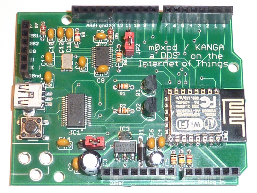
Kanga UK and I have been developing a new board and I can bring you some pictures of the first engineering sample...


You can well see it is an engineering sample, because I'm squeezing the wrong size packages into locations (quarter Watt resistors where eighth Watt components should be, etc) and using a mishmash of different component types, but you'll forgive me, I'm sure.

The new design presents the Expressif ESP8266 device on an Arduino-sized board, supported by a full USB programming interface and power supply.

I should be careful to explain - this is not a "shield". It does not sit on top of an Arduino. It REPLACES the Arduino. It IS the processor - and a whole bunch more...

Of course, there's all the interfacing headers you'll need to connect it to other expansion devices ("shields") from the Arduino ecosystem. This is nothing new - it is already available in commercial platforms out there, such as the WeMos D1 R2 (indeed, I made this new board largely compatible with WeMos' digital I/O pin allocations).

Of more relevance to fellow amateurs, this new board includes a DDS system, capable of generating stable, controllable RF, using the AD9834 device.

You have here a powerful processor - significantly more capable than that on (e.g.) the basic Arduino UNO - with a full, on-board DDS system. All with access to the advantages of the Internet (time servers, geolocation, remote control, ...). All on one little board.

The overall architecture is seen in the image below...


The output from the DDS module is taken to the header on the upper left hand edge of the board in the orientation of the photo above - which is the m0xpd RF bus I've defined previously for other shields. This facilitates the first application for the new board: to implement a beacon system, using the Kanga/m0xpd Sudden Transmitter shield, which can simply plug on top of the new board to make a complete beacon assembly.

The USB interface is implemented using a genuine FTDI chip, with the hope that interface problems should be minimised. However, I've just had all sorts of problems after upgrading the operating system of my MacBook Air to El Capitan, after which it seems incapable of operating reliably with ANY external peripheral - not just the FTDI devices.

The new board has flexible power supply options. It can be powered off the USB connection. It can derive power from the 5V supply from the Sudden Tx shield in the beacon application described above or it can be powered through the d.c. power jack visible at bottom left of the photo.

Of course - the collaboration with Kanga signals that this board - or the final production version - may soon be available for purchase as a kit. With the experience of the m0xpd Si5351 shield, we have discovered that many Kanga customers are not great fans of surface mount technology. Accordingly, this system has been designed with the intention that key SMD elements could be delivered pre-fitted...


leaving the kit buyer to fit only thru-hole components, one large voltage regulator and the ESP8266 module itself.

Here, finally, is the engineering sample, plugged into a Sudden Tx shield (itself a prototype) for the very first time to run my beacon code as a "stack"...


The little OLED display on the breadboard at bottom right is there just as a sign of life.

Although not so good these last two or three days, when it has been harder to burst far out of Europe, the same technology has been running WSPR and QRSS all over the globe for the past couple of weeks, as recent posts testify.

I hope that this new board might tempt some more radio hams to look toward the ESP8266 and the"Internet of Things" for inspiration and fun.

...-.- de m0xpd


Wednesday, 24 August 2016

USB Mini Breakouts

If, like me, you ever fool around with USB hardware and choose to do so in the context of solderless breadboards, you might well need a little breakout board for one of the several types of socket - in my present case the USB mini-B receptacle.

There are, of course, lots of lovely commercial ways to scratch this itch, available - for example - on our favourite auction site...


but I wanted one now, rather than in a day or two's time (or longer, if it had to take the slow boat).

Of course, I'd been getting by with the usual solution of a butchered cable with a type A plug at one end and some pins on the end of bare tails I'd made at the other...


but I wanted to get rid of this 'trailing wire' and fit a neat socket.

I had some surface mount mini-B receptacles in the junk box and noticed that the connector pitch was close enough to the 0.95mm spaced pads on one side of a 10-pad SOT23 DIL carrier...


So, with a little judicious bending of the outer pair of pins, a 5-way strip of male header pins and some solder, I soon had my own USB mini breakout...


Here it is in action on the beacon...


I don't think I'll even bother to order any from the Far East - they're too easy to make!

...-.- de m0xpd


Friday, 19 August 2016

ESP8266 Geolocation

The ESP8266 device, used as the heart and soul of my new beacon, knows its place in the world...


This post describes a couple of techniques for 'Geolocation' on the ESP8266 and uses them to derive the location information my beacon needs to broadcast (e.g.) a valid WSPR message.

Readers may remember I grafted a GPS module onto an earlier beacon system here in the shack - mainly for time synchronization - but don't know how much trouble I had with it (a north facing window made GPS reception VERY difficult).

Having my new beacon sat on the 'Internet of Things' opens up a new possibility for obtaining not just time (which I've already reported) but also position information, using geolocation. So - I decided this was a worthy avenue for experiment, both for the practical end of getting the location by other means than GPS and as an interesting learning exercise.

It turns out that Geolocation, by the methods I'll describe below, is a standard alternative to positioning via GPS in those places where a satellite signal cannot be obtained (indoors, underground etc.).

I'll describe two broad methods - and present working ESP8266 code to illustrate each.

The first uses your own IP address to provide a rough estimate of location, using a service such as Freegeoip. Adafruit has posted a very good example of how to use this service here and I've modified their code to provide a stand-alone application for the ESP8266.

The code on the github link above is presented as a sketch for the Arduino IDE. You'll need to modify it to include your own WiFi network's ssid and password before it will work. It will print the results into a Serial Monitor window (at 115200 baud).

I included an elaborated version of this code in my beacon, to generate the following location estimates on the little screen...

  
Clearly, it knows I'm in Manchester (!), but the map reference turns out to be quite a bit off...


It places me at a location about 8 km away from my actual QTH, as seen in the map above (the erroneous location is seen - not my home - this isn't an invitation for thieves).

All this might not matter too much, but for the fact that it is actually in the wrong (six-character) Maidenhead locator square...


This shows an incorrect placement in IO83uk when actually I'm in IO83tk.

Not too serious - but a reflection of the poor absolute accuracy of the location estimation afforded using this first IP-based Geolocation method. Remember - it is 8km out. In fact, as I write, freegeoip.net is returning a location estimate which is much poorer than that - bang in the middle of London!

An alternative method clearly is needed to accurately resolve the correct locator square.

The second method, known as the WiFi positioning system or WPS, uses a scan of all the WiFi Access Points visible to the ESP8266. The result of this scan is uploaded to a Geolocation API, such as those offered by Google or Mozilla.


Both these services are entirely free to use, but Google make you jump through a lot of hoops to get an API Key. Mozilla is hoop-free.

I've written some code which shows how to access these services using the ESP8266 here.

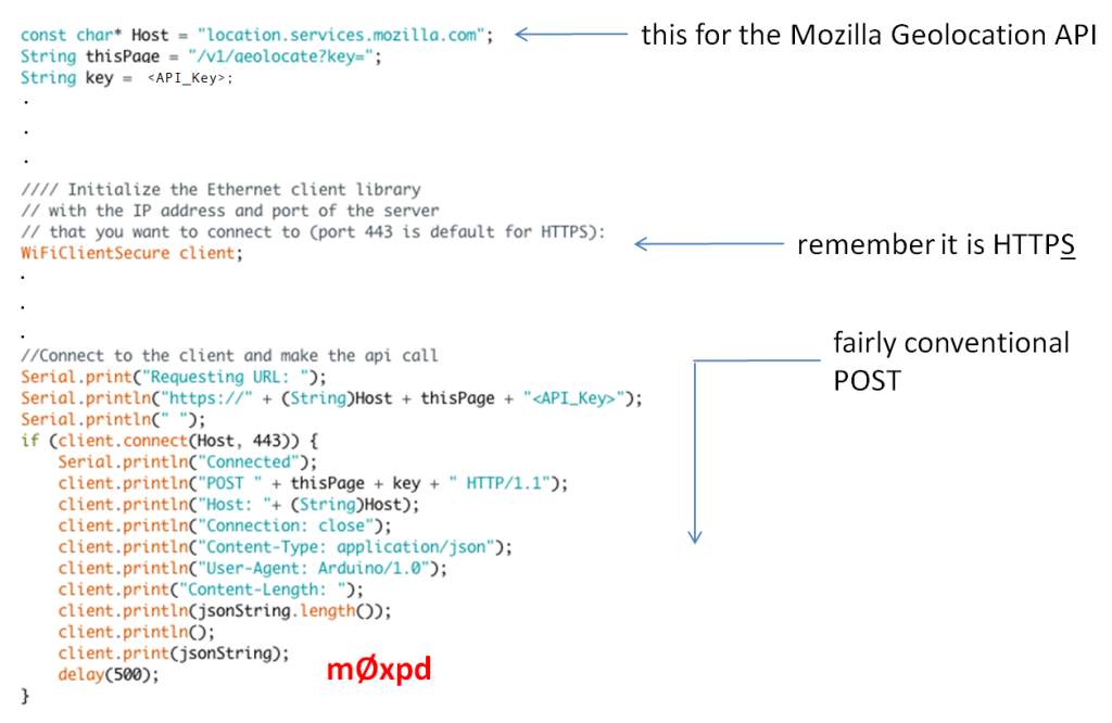
The important part of the sketch is shown in this extract...

 
After setting up the important credentials for accessing the API (Host, Page and access key), the HTTPS client needs to be instantiated (it needs to be the Secure version of the WiFi client - so this won't be easy or even possible to run on a lesser processor than the ESP8266).

After this, the POST is fairly conventional (see, for example, the example at the bottom of this page) but it did take me a long time to figure out exactly how to get it working!

Here's the beginning of the result of the WiFi scan, as produced at my QTH, showing some of the WAPs visible here...


It is in the JSON format produced by the code and required for submission to the Geolocation APIs.

WPS databases operate in context of the mobile telephone industry and require that the header includes some parameters which spoof the API into believing that the request is coming from a mobile device with GSM capability. I used a Mobile Country Code and Network Code associated with a local network provider in the UK (which I looked up in a table). If you're not in the UK, you should probably choose a different MCC and MNC.

I also used the ArduinoJson library to handle the result from the Geolocation API.

With this method, location results have an accuracy of order metres, so an elaborated version of the code was implemented in my little proto-beacon...


Now we're in the building (actually, we're in a house at the bottom of my garden, but that sort of error I can live with).

With location and time (from the NTP servers, as previously reported) I have all the ingredients required to automatically generate a WSPR message, instead of going through the chore of generating it ahead of time in a command-line utility on the PC and uploading it as a constant into the beacon...

I looked at Gene, w3pm's on-line materials, among which are several Arduino sketches including a function 'void wsprGenCode()' which generates WSPR messages. This works perfectly well, but calls several other functions and isn't the easiest item to work with.

Fortunately, a further quick search produced John Newcombe's elegant WsprMessage c++ class, which I am now using. It is producing my WSPR message very efficiently...


Credit where it is due: both Gene's function(s) and John's class (/library) draw heavily on the work of Andy Talbot, g4jnt, who has produced a detailed explanation of the WSPR coding process.

The entire beacon now is literally turn-on and go, in any location with a WiFi connection. It ran last night on 30m with an unusually strong performance into S America...


although this seemed to be at the expense of contacts into the antipodes.

I hope others are as excited by this collision between amateur radio and the Internet of Things as I am - it seems alive with possibilities.

...-.- de m0xpd