I took the well-executed PCB which - unusually for Rex - had through hole mounting for the components rather than the 'Limerick' construction that recently I've come to associate with him...

Following the excellent instructions, I whittled away the PCB at the business end, to make the probe easier to probe and poke into awkward places, then added the four components...

Then I just needed to add the probe tip and the connecting wires...
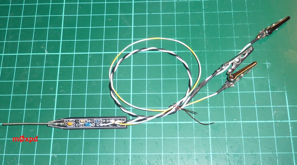
Actually, I tested the whole assembly at this point - but let's pretend I just went confidently ahead and sealed it all up.
I built up a few layers of heat shrink at the tip...

... before covering the whole thing in a protective sheath, which prevented my fingers messing up sensitive measurements by touching the wrong (high impedance) place.

It isn't going to win a beauty prize - but then neither am I.
To check the new little toy in operation, I turned to another gift from Rex (kindly donated at last year's FDIM) - a Dummy Load (which makes a nice addition to my collection)...

I threw some RF at the dummy load and probed about at the top of the resistors, having first connected the new RF probe to an ugly old digital multi-meter of unknown parentage.

As you see from the little inset photo of the 'scope screen, I'd set the RF level to 1V peak. The RF probe was indicating a voltage of 0.656 on the multi-meter but, given the 1V peak on the resistors, it "should" have been reading 0.707106.... V.
The circuit of this RF probe is a shunt design of the form regularly appearing in ARRL handbooks (etc). My most recent copy is the 2009 edition, in which it appears as Fig 25.9 (D) on page 25.9.
The series combination of a 3.9 M and a 220 k resistor as used on this probe gives 4.12 M Ohms.
When this resistor drives a meter WITH A 10 MEG OHM INPUT IMPEDANCE, then the probe will scale the peak voltage detected on its diode to the correct RMS voltage for a SINUSOIDAL input waveform.
This is because of the potential divider action between the meter's input impedance and the source impedance formed by the 4.12 M Ohm resistor:

Obviously - and fortunately - my multi-meter of unknown parentage (actually it came from a Red Rose Winter Rally just down the road at the George Carnall Sports Centre a few years back) must have an input impedance close to 10 M Ohm. I tried it on another random digital multi-meter and it returned 0.696 V. Obviously, these meters have input impedance close enough to 10 Megs to make the approximation useful.
On my Solarton 7050 DVM (with more than 1000 M Ohm specified input impedance) 1.009 V was observed - i.e. the probe became a peak voltage probe!
Neat little toy. Thanks Rex - for everything.
Thinking about it, it must be almost time for the next Red Rose Winter Rally...
Yes - see you next Sunday!
...-.- de m0xpd

No comments:
Post a Comment