No sooner than I'd completed the modifications which turned my Leslie 125 into something approaching a 145, I ran into a problem...
Without warning, the amp popped its fuse. On investigation, it turned out to be the mains transformer. I could measure resistances of the order of tens of Ohms where there ought to be isolation - between the secondary, the primary and the core. Also, the secondary centre tap was no longer in the centre - in impedance, at least. Obviously, where once there was insulation there were now some conducting paths.
Maybe I've been lucky, but in 35+ years of tinkering with electronics, I never met a bad transformer before. They just work - or so I thought!
Just my luck - it is easy to find replacement transformers for a 122 or a 147 - they're stock items (especially in the US). But I couldn't find a source for a replacement for my 125 amp's transformer for love or money. Fortunately, Simon at BLS Electronics made me a new one, re-using the pressed steel shrouds from the old unit.
Here are the remains of the original, next to the new transformer...
Usual disclaimer - I don't know Simon or BLS Electronics from Adam - but they did a great job at a great price. The new transformer is now in place and everything was working fine until...
After having played though the newly restored speaker for best part of a day, I noticed that the lower rotor was creeping round in chorale. It would run in tremolo, but ground to a halt at the lower speed. I fiddled about and noticed that if I pushed up the rotor on its spindle (on which it is a friction fit), the rotor would turn again. But, after a few more hours, the old sluggish behaviour returned. Time to strip down the lower rotor...
Here's an exploded image of the rotor from the user's manual...
The drawing indicates that the bearing plate (#511-2 in the drawing above) is fixed in place from beneath the cabinet by two screws. I tilted the speaker enough to get a short screwdriver to the screws, but they didn't have any heads!
Instead, I saw the ends of the screws in some T-nuts.
Despite expectations, the bearing unit in my 125 is fixed in from inside, on spacer blocks...
From what I could see, this is how it was made - no evidence of modifications of any kind.
I could also quickly see what was slowing down the rotor - especially when it was "low" on the spindle. Here's the top of the bearing assembly, in the middle of which you see the grommet which goes through in the middle of the bearing (numbered 510-3 in the drawing from the user's manual)...
According to the user manual (see exploded drawing above) another grommet (513-2) at the bottom of the rotor bears on this grommet to support the weight of the rotor. Looking at the bottom of the rotor reveals that it had been scraping against the bearing housing, generating the drag that brought the whole assembly to a halt...
Also, I noticed that the bearing housing was distorted in such a way as to bring the bearing lower in the housing - adding to the possibility that the rotor grommet could foul on stationary parts. Look at the deformation in the lower housing component...
The fix was obvious - I needed to keep the rotor higher up the spindle, so the rubber grommet at the base was free. I took a "belt-and-braces" approach and made three interventions.
First, I cleaned and assembled the bearing, avoiding the distortion in the photo above, fractionally moving the ball race and its bearing surface higher.
Second, I inverted the grommet in the bearing, so its unworn lower part is now at the top...
Third, I added a washer between the grommet in the bearing and that on the rotor (between which there is no significant relative movement) to make double-sure there is real clearance between fixed and rotating parts.
The result? The speaker is transformed, with working chorale and much faster acceleration to tremolo. It has been running all day without a hint of trouble. I hope that has fixed it for good.
I do have some outstanding jobs, most important of which is to cure a rattle/buzz coming from part of the rotor - there's a flared piece (made, I think, of expanded polystyrene) which is moving relative to the other wooden parts and - in so moving - buzzing. I've put some Blu Tack there as a temporary fix.
Excuse me - I must go back to the organ now - this speaker sounds SO good.
...-.- de m0xpd
Sunday, 1 July 2012
Tuesday, 5 June 2012
Leslie 125 Modifications
Readers will be aware that I picked up an old Leslie 125 from ebay, just before Christmas. I always had plans for the speaker, but my hand was forced into action when it suddenly started to hum loudly and then popped its fuse - seemed a good cue for a rebuild of the amp and for the modifications I had in mind.
Here's the original speaker, nervously awaiting "surgery"...

My plan was to add a rotating horn, controlled by the MTCLogic speed controller, to take the speaker far from its humble origins to a baby 145. My purpose was two-fold; first to educate me in the ways of Leslies and second to avoid the expense of paying for a "real" 145 (the 125 cost me 31 pounds - you can't buy a 122, a 147 or a 145 for ten times that).
The most obvious external feature would be the additional "slots" in the top of the cabinet - so out came a router...

The result was pleasing enough - my compound cuts with two router bits made a passable impression of real louvres...

Whilst the sun still shone in the outdoor woodwork shop, I turned my attention to fitting some battens to hold the new top shelf. They were made from "available material" - the material having made itself available in a skip next to a building project - I hate paying for lumber...

With the battens in place, I could fit my new top shelf...

A little more modification gave me a pretty authentic back - with the original labels that proclaim the speaker's lowly origins as a 125...

Woodwork completed, I turned my attention to the electronics.
The can capacitor in the power supply filter was replaced, along with some other "mission-critical" capacitors and a power resistor in the power supply filter. There was also a capacitor missing in the amp - bypassing the output transformer's primary at HF and therefore (I suppose) important to HF stability of the circuit.
Also, I added a socket to take 240V and switched 240V to the speed control electronics...

Here's the amp with its new socket on the side...

With the amp running again, I needed a crossover unit to divide the signal between the original 12 inch unit and the new horn. The stock Leslie crossover looks a bit ramshackle, being built up on a piece of hardboard...

I knocked up some brackets to mount the crossover safely on the side wall of the enclosure...

Also seen in the photo above is a (massively over-specified) 240 - 110V transformer, which I'm using to provide the US mains voltage for the MTCLogic speed controller. It is important that I keep this in "stock" condition, as this speaker will be a test-bed for my future work on the new speed control system.
The modified 125 sounds like a dream - it is a joy to use and a pleasure to look at! There are a few more jobs to do (like replacing that massive transformer with something more appropriate and making a motor cover for the top motor to seal the main enclosure), but its is so good to play that these details can wait!
My thanks to George Benton of Benton Electronics for his generosity in sourcing parts, his expertise and his friendship.
...-.- de m0xpd
Here's the original speaker, nervously awaiting "surgery"...
My plan was to add a rotating horn, controlled by the MTCLogic speed controller, to take the speaker far from its humble origins to a baby 145. My purpose was two-fold; first to educate me in the ways of Leslies and second to avoid the expense of paying for a "real" 145 (the 125 cost me 31 pounds - you can't buy a 122, a 147 or a 145 for ten times that).
The most obvious external feature would be the additional "slots" in the top of the cabinet - so out came a router...
The result was pleasing enough - my compound cuts with two router bits made a passable impression of real louvres...
Whilst the sun still shone in the outdoor woodwork shop, I turned my attention to fitting some battens to hold the new top shelf. They were made from "available material" - the material having made itself available in a skip next to a building project - I hate paying for lumber...
With the battens in place, I could fit my new top shelf...
A little more modification gave me a pretty authentic back - with the original labels that proclaim the speaker's lowly origins as a 125...
Woodwork completed, I turned my attention to the electronics.
The can capacitor in the power supply filter was replaced, along with some other "mission-critical" capacitors and a power resistor in the power supply filter. There was also a capacitor missing in the amp - bypassing the output transformer's primary at HF and therefore (I suppose) important to HF stability of the circuit.
Also, I added a socket to take 240V and switched 240V to the speed control electronics...

Here's the amp with its new socket on the side...

With the amp running again, I needed a crossover unit to divide the signal between the original 12 inch unit and the new horn. The stock Leslie crossover looks a bit ramshackle, being built up on a piece of hardboard...

I knocked up some brackets to mount the crossover safely on the side wall of the enclosure...

Also seen in the photo above is a (massively over-specified) 240 - 110V transformer, which I'm using to provide the US mains voltage for the MTCLogic speed controller. It is important that I keep this in "stock" condition, as this speaker will be a test-bed for my future work on the new speed control system.
The modified 125 sounds like a dream - it is a joy to use and a pleasure to look at! There are a few more jobs to do (like replacing that massive transformer with something more appropriate and making a motor cover for the top motor to seal the main enclosure), but its is so good to play that these details can wait!
My thanks to George Benton of Benton Electronics for his generosity in sourcing parts, his expertise and his friendship.
...-.- de m0xpd
Sunday, 18 March 2012
MICROCHIP disappointments
I have spent the last seven days frustrated by failures of MICROCHIP PIC devices.

I don't mean "failures" in the sense of heat and smoke. I don't mean "failures" in the sense of faulty logical operation (we didn't get that far). I mean "failures" in the sense of not doing what the manufacturer says it can do.
Before we start complaining, let's be clear - I am a fan of PICs. I have been using them since the 90s. As readers of this blog will know, I've used them in lots of radio-related projects (such as the multi-mode beacon) and more recently in the virtual organ. I've also used them "at work" and in real-world projects, most recently the MTCLogic controller. I am a fan and - perhaps - being a fan makes it all the more disappointing when things go bad...
It started with a 16F628A. I had found some old code on the 'net and, since it was written for the 628A, I thought I'd run it in that device. So I got a sample, only to be frustrated by it.
I found that I was completely unable to program the device using either my ICD2 or my PICKit2. [Incidentally, the claim that PICKit2 DOES support the 16F628A is made here (where it does remind users that debug is impossible without an additional component)]. Most of the time, I got a failure on verification at a very low address, suggesting that no programming had happened at all. Occasionally, a few locations verified before failure. Once (in an afternoon trying to debug the issue) I got a successful programming.
Not good enough!
I could program the device in my PICStart Plus - but I have grown used to in-circuit serial programming and wanted to use it here. Besides, MICROCHIP and all their documentation and code (I'm using MPLAB 8.7) CLAIM that this is possible.
A quick look on the internet persuaded me that I'm not the only person who has fallen foul of this discrepancy between marketing claim and experienced engineering reality, so I gave up and ordered a more modern 18-pin device - the 16F88.
On delivery I found that the 16F88 was up for being programmed with either ICD2 or PICKit2. Great! Until I tried something else which is CLAIMED to be possible - using debug mode on the 16F88 with the PICKit2...
Once again, this doesn't work - most frequently in the following failure mode...

(occasionally I could get past that point, but the subsequent debug operation did not work). I looked on the 'net and - you guessed it - this is a known problem.
I didn't want to have to change device again, so I tried debugging with the ICD2. That works.
I don't mind failure per se. I do mind when somebody claims that it is possible to... when it simply is NOT possible to. I don't care if it once worked for somebody. All I care is that it did not work for me and has wasted my valuable time.
Time which is far too valuable to waste posing questions like "why change the name of timer 0's interrupt enable flag from the simple "T0IF" (12F675) to the wasteful, redundant "TMR0IF" (16F88)". I suppose I should be happy and contented by the fact that the 16F88 does manage to do (most of) what is claimed for it.
...-.- de m0xpd

I don't mean "failures" in the sense of heat and smoke. I don't mean "failures" in the sense of faulty logical operation (we didn't get that far). I mean "failures" in the sense of not doing what the manufacturer says it can do.
Before we start complaining, let's be clear - I am a fan of PICs. I have been using them since the 90s. As readers of this blog will know, I've used them in lots of radio-related projects (such as the multi-mode beacon) and more recently in the virtual organ. I've also used them "at work" and in real-world projects, most recently the MTCLogic controller. I am a fan and - perhaps - being a fan makes it all the more disappointing when things go bad...
It started with a 16F628A. I had found some old code on the 'net and, since it was written for the 628A, I thought I'd run it in that device. So I got a sample, only to be frustrated by it.
I found that I was completely unable to program the device using either my ICD2 or my PICKit2. [Incidentally, the claim that PICKit2 DOES support the 16F628A is made here (where it does remind users that debug is impossible without an additional component)]. Most of the time, I got a failure on verification at a very low address, suggesting that no programming had happened at all. Occasionally, a few locations verified before failure. Once (in an afternoon trying to debug the issue) I got a successful programming.
Not good enough!
I could program the device in my PICStart Plus - but I have grown used to in-circuit serial programming and wanted to use it here. Besides, MICROCHIP and all their documentation and code (I'm using MPLAB 8.7) CLAIM that this is possible.
A quick look on the internet persuaded me that I'm not the only person who has fallen foul of this discrepancy between marketing claim and experienced engineering reality, so I gave up and ordered a more modern 18-pin device - the 16F88.
On delivery I found that the 16F88 was up for being programmed with either ICD2 or PICKit2. Great! Until I tried something else which is CLAIMED to be possible - using debug mode on the 16F88 with the PICKit2...
Once again, this doesn't work - most frequently in the following failure mode...

(occasionally I could get past that point, but the subsequent debug operation did not work). I looked on the 'net and - you guessed it - this is a known problem.
I didn't want to have to change device again, so I tried debugging with the ICD2. That works.
I don't mind failure per se. I do mind when somebody claims that it is possible to... when it simply is NOT possible to. I don't care if it once worked for somebody. All I care is that it did not work for me and has wasted my valuable time.
Time which is far too valuable to waste posing questions like "why change the name of timer 0's interrupt enable flag from the simple "T0IF" (12F675) to the wasteful, redundant "TMR0IF" (16F88)". I suppose I should be happy and contented by the fact that the 16F88 does manage to do (most of) what is claimed for it.
...-.- de m0xpd
Sunday, 11 March 2012
Volte-Face on Toner Transfer
Politicians do it all the time - so why shouldn't I? I've made a u-turn. A 180. A policy reversal.
I guess it really started this week, when I was trying to make up a little PCB for work - only about an inch square with a few SMT components on it...

However, it seemed to lie at the extreme edge of the abilities of my "Toner transfer" backyard PCB manufacturing technology (blogs passim). It took me a couple of tries to produce a satisfactory batch of boards and I just don't have that much time to waste!
Fortunately, a mention on the G-QRP Yahoo Group this week had drawn my attention to a website, enticingly called "Blondihacks", produced by a talented engineer who rejoices in the name "Quinn Dunki". The particular link was to Quinn's description of PCB production, in which she summarises her methods for producing PCBs using pre-coated photosensitive boards. Quinn's descriptions and the frustrations of my week persuaded me to give it a try - so I ordered some board and developer from Rapid (who - once again - lived up to their name).
OK - here we go... Deep intake of breath... I hereby renounce Toner Transfer methods of PCB production. They may be cheap, but they are rubbish, compared to what can easily be achieved using photo methods. The quality of my first optical board comfortably exceeded anything I've ever made using toner transfer...

Don't waste your time with irons or laminators. Don't waste time trying to get rid of those irritating chalky deposits from glossy photo paper that get trapped between traces, that fill holes and that mess up fine detail. Don't waste time trying to use old magazines and suffer porosity in the etch resist and consequent discontinuities in the copper. Get yourself kitted out with some photographic technology. Do you detect a whiff of the zeal of the newly converted? That's me!
All I used for exposure was a UV-rich florescent tube intended for aquaria and an old picture frame. I'll work it all up into a "proper" light box eventually!
I didn't follow Quinn's advice about etching - my bubble-tank full of ferric chloride has never been a problem.
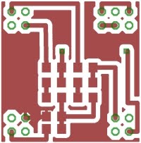
Incidentally, the PCB in question is a development environment for the MTCLogic controller - it replaces (by plugging into its DIL socket) the 12F657 PIC with a richer processor, with extra I/O and the luxury of a CCP module - just right for PWM applications...

As you see, there's MIDI input and output, an ICSP interface (here seen with an FCC68 adapter going to the ICD2, but equally at home plugged directly into my PICkit2), a couple extra analog inputs (by which system parameters can be adjusted using the prsets) and 4 digital inputs (to select options). As you gather, there are lots of exciting developments in hand on the Leslie controller front!
Incidentally, I like the way our American cousins say "a couple extra analog inputs...", as distinct from the English equivalent "a couple OF extra analog inputs...".
Anyone want a knackered laminator?
...-.- de m0xpd
I guess it really started this week, when I was trying to make up a little PCB for work - only about an inch square with a few SMT components on it...

However, it seemed to lie at the extreme edge of the abilities of my "Toner transfer" backyard PCB manufacturing technology (blogs passim). It took me a couple of tries to produce a satisfactory batch of boards and I just don't have that much time to waste!
Fortunately, a mention on the G-QRP Yahoo Group this week had drawn my attention to a website, enticingly called "Blondihacks", produced by a talented engineer who rejoices in the name "Quinn Dunki". The particular link was to Quinn's description of PCB production, in which she summarises her methods for producing PCBs using pre-coated photosensitive boards. Quinn's descriptions and the frustrations of my week persuaded me to give it a try - so I ordered some board and developer from Rapid (who - once again - lived up to their name).
OK - here we go... Deep intake of breath... I hereby renounce Toner Transfer methods of PCB production. They may be cheap, but they are rubbish, compared to what can easily be achieved using photo methods. The quality of my first optical board comfortably exceeded anything I've ever made using toner transfer...

Don't waste your time with irons or laminators. Don't waste time trying to get rid of those irritating chalky deposits from glossy photo paper that get trapped between traces, that fill holes and that mess up fine detail. Don't waste time trying to use old magazines and suffer porosity in the etch resist and consequent discontinuities in the copper. Get yourself kitted out with some photographic technology. Do you detect a whiff of the zeal of the newly converted? That's me!
All I used for exposure was a UV-rich florescent tube intended for aquaria and an old picture frame. I'll work it all up into a "proper" light box eventually!
I didn't follow Quinn's advice about etching - my bubble-tank full of ferric chloride has never been a problem.
Incidentally, the PCB in question is a development environment for the MTCLogic controller - it replaces (by plugging into its DIL socket) the 12F657 PIC with a richer processor, with extra I/O and the luxury of a CCP module - just right for PWM applications...

As you see, there's MIDI input and output, an ICSP interface (here seen with an FCC68 adapter going to the ICD2, but equally at home plugged directly into my PICkit2), a couple extra analog inputs (by which system parameters can be adjusted using the prsets) and 4 digital inputs (to select options). As you gather, there are lots of exciting developments in hand on the Leslie controller front!
Incidentally, I like the way our American cousins say "a couple extra analog inputs...", as distinct from the English equivalent "a couple OF extra analog inputs...".
Do yourself a favour - get yourself down to Blondihacks for some well crafted, witty American writing surrounding some interesting and educational projects.
Do yourself another favour - ignore any previous advice seen on these pages advocating toner transfer.
Anyone want a knackered laminator?
...-.- de m0xpd
Sunday, 19 February 2012
Top Shelf
As threatened last week, I gathered all the components of a top shelf for my Leslie 125 together and made a trial assembly...

You can see at top left the MTCLogic controller, a power strip providing 110V from an isolation transformer, the motor, the horn and the belt tensioning arrangement, all mounted on a piece of 19mm MDF.
Here's the single-speed Leslie motor in close-up...

I turned up some spacers (not visible above - they're hiding under the rubber mounts) from mild steel to raise the motor up to the correct height above the board to match the pulley on the horn, which you can see in the next photo...

Also visible is the stock Leslie idler pulley, which tensions the belt. The motor and the speaker are in the correct positions, copied from the layout of a Leslie 145 - but I improvised with positioning of the idler wheel.
Here'a a close-up of the controller. It is held in place for testing with my customary blobs of Blu Tack...

The system works perfectly with our new controller (he says, swelling with pride). I also tried it with some of the competition...

This is a unit from Caribbean Controls. I'm pleased to be able to say that there is no competition as to which speed controller I'll build into the modified 125. I'm even more pleased to be able to say that the choice is made entirely on merit!
...-.- de m0xpd

You can see at top left the MTCLogic controller, a power strip providing 110V from an isolation transformer, the motor, the horn and the belt tensioning arrangement, all mounted on a piece of 19mm MDF.
Here's the single-speed Leslie motor in close-up...

I turned up some spacers (not visible above - they're hiding under the rubber mounts) from mild steel to raise the motor up to the correct height above the board to match the pulley on the horn, which you can see in the next photo...

Also visible is the stock Leslie idler pulley, which tensions the belt. The motor and the speaker are in the correct positions, copied from the layout of a Leslie 145 - but I improvised with positioning of the idler wheel.
Here'a a close-up of the controller. It is held in place for testing with my customary blobs of Blu Tack...

The system works perfectly with our new controller (he says, swelling with pride). I also tried it with some of the competition...

This is a unit from Caribbean Controls. I'm pleased to be able to say that there is no competition as to which speed controller I'll build into the modified 125. I'm even more pleased to be able to say that the choice is made entirely on merit!
...-.- de m0xpd
Sunday, 12 February 2012
In a Spin
Aside from admiring, owning and using them, your humble servant is now active within the global economy of Leslie Speakers, having jointly developed an accessory which is commercially available. More of that sordid, mercenary semi-professionalism later. First, true to my Ham credentials, I'd like to share some details of my new Leslie interface, just for the love of it.
Readers have learned how I got my first Leslie, an 825, from Bob, just down the M56 in Chester. A couple of weeks before Christmas, I got another Leslie from another Robert, a little further west in Holywell. I'm pretty sure that the relative remoteness of Chester and (particularly) Flintshire kept the prices down to my beer-budget levels.

The new (old) Leslie is a 125 - similar to the 825 in that is has only a single speaker (but that's about to change - watch this space). The 125 is, however, critically different in at least three important respects. Firstly, it has a veneered wooden enclosure (rather than the ugly "Tolex" vinyl covering of the ProLine 825) - it LOOKS like a Leslie. Secondly, it has a valve(/tube) amplifier, with all the romance that entails. Thirdly, it uses a different interface to the outside world.
The 825 uses Leslie's "9 pin" interface, as described in this previous post. It achieves speed control by a simple, low voltage switching scheme, ready for plug 'n play connection to my homebrew half-moon switch.
The 125 uses an older interface standard, called "6W". The 6 indicates the fact that there are only 6 conductors in the cable to the speaker (and 6 pins on the special, expensive Amphenol connectors). The "W" actually stands for Wurlitzer, in order to differentiate from another contemporary six-pole Leslie interface, "6H", in which the "H" meant Hammond. The 6H interface was used for - you guessed it - Hammonds, as exemplified by the Leslie 122. The 6W interface, developed from a Wurlitzer wiring standard, is also called the "Universal" interface and is used for other applications, as in the Leslie 147. These two interface standards are dangerously INCOMPATIBLE, yet they share the same physical layer in the special "6 pin" connector cable, which is used in both standards.
Here, for my own records as well as your edification, are the pin assignments in the 6W standard...
The colours refer to the cores in a real Leslie cable.
Note the apparently inoccuous pins 2 & 5, connected to the Motor Relay. In order to switch between the two available speeds ("chorale or tremolo"), one has to apply 240V AC between pins 2 and 5 (in the UK at least). Speed control certainly isn't a "simple, low voltage switching scheme" and it implies switching mains electricity. No voltage gives tremolo (the fast rotor speed) and 240V gives chorale (the slow speed).
Call me a wuss if you like, but I have a pretty well-developed fear of high voltage electricity. It all started when my childhood friend, Paul Sibley, tried to stop the smell caused by a budgerigar feather burning on the element of a small electric fan heater. Paul used a pair of scissors to remove the feather with predictable results. He flew across the kitchen at altitude of about six inches and slammed into the opposite wall. Mr Sibley was a successful builder who had built his family an impressively proportioned home, so Paul's trans-kitchen flight was a long one. He survived and I learned what has proven to be a useful life lesson.
With all the baggage of burning budgie feathers, I wasn't about to go switching mains voltages on my virtual organ console. I don't think the guitar pickup selector switch in my homebrew half-moon switch would have handled 240v AC - much less, into slightly inductive loads. So - a safer switching scheme was indicated...
Of course, I could have simply used a relay to switch the voltage to the motor relay (big fleas have little fleas upon their backs...) and used the Telecaster switch to energize the local relay coil at low voltage. That, however, wasn't entirely true to the spirit of the ideas brewing in the back of my mind for more flexible speed switching options, including 9-pin, 6-pin and maybe even 11-pin interface compatability, so I added a little electronics.
Here's the low-voltage aspects of my speed control circuit - it is based on a somewhat over-specified relay from Maplin (which required me to learn again for the umpteenth time how to create a new part for Eagle). The design includes a stabilized 12V supply (not strictly needed for the switching operation, but important for the rest of my design, as you'll see in a moment), which is at the top of the schematic below.

I've edited out all the high voltage parts of the circuit. I don't want to be held responsible for people who haven't learned the consequences of burning budgie feathers.
Here's the switching circuit in the flesh...

Still glowing with the success of my pre-amp for the 825, with its HF shelving filter, I made another identical circuit for use with the 6W interface...

All these printed circuit boards are all very well, but they only become a practically useful system when placed in an enclosure with the appropriate connectors. In sourcing a suitable box I learned that some of Maplin's enclosure range is to be discontinued - I hope this isn't yet another stage in the long, drawn-out demise of this once-useful source of components. (For overseas readers, Maplin is a high street retail chain filling the spot once occupied by Tandy - the UK version of Radio Shack. Until five or so years back, Maplin rivalled the big "trade" players in component supply with on-line and high street options. The demise of hobby electronics (indeed, of any practical pursuit) and the nonsense of trying to provide it on the high street has driven Maplin's metamorphosis into yet another consumer electronics / tech store. I doubt they will survive much longer.)
Anyway, here are some shots of my finished 6W interface, allowing the 125 to be connected to my virtual organ (i.e. a computer soundcard) or anything else which can produce close-to line level audio into high impedance.

The big red switch turns on the whole shooting match (including the Leslie) and the two controls on the front are for volume and HF boost.There are internal jumpers selecting 0, 10 or 20 dB overall gain. On the rear are mains inlet via an IEC socket, the 6-pin chassis socket (I splashed out and purchased a 32.5mm hole punch to add to the collection), audio input via 1/4 inch jack and speed control via a 3-pin DIN (as used on my other "pre-amp"). It works perfectly and makes hooking up the 125 (or any other Leslie using the 6W interface) a walk in the park.
Here is the finished 6W interface unit, sitting atop the 825 (the 125 is on the other side of the room).

Now to return to the commercial world...

I was chatting with Hammond and Leslie expert George Benton, after reading of his adventures using a Hammond Super B console as controller for a virtual organ. George had seen the games I was playing with PICs in an organ context and asked if I'd like to join in developing a speed controller for Leslie speakers. I accepted, thinking I'd learn from the experience and from friendship with George - both have turned out to be the case.
First, a little explanation.
Early Leslie speakers (the 21H, 22, 22H, 22R, 31H, 44W, 45, 46, 47and 51) were single speed (or, at least, single speed plus "stationary"). Later models evolved to the more familiar two-speed operation mentioned above. It will come as no surprise to hear that the old, single speed models are coveted and valued for their special, desirable properties, real and imagined. Prices soar accordingly. Despite this, owners of single speed units also like the two-speed feature, so opportunity exists for electronic speed controllers able to convert a single-speed unit to two-speed operation. A number of such controllers are available.
George had the bare bones of such a system but needed to develop software - enter yours truly.
Our Leslie speed controller is a fairly standard motor control application, using Pulse Width Modulation techniques. The motor is placed in an H-bridge, formed of IGBTs, under the supervision of a PIC microcontroller...

Although Motor Control is a standard PIC application, we chose (for legacy reasons) to use a very simple 8-pin PIC with no hardware Capture/Compare/PWM module. This made the entire project a matter of trying to squeeze a quart into a pint pot. Not in terms of memory capacity or computational load - rather in handling the time constraints imposed by the interrupt-based software PWM modulator I developed.
The single-speed motors are built to run at "tremolo" speed when driven by 110V, 60Hz, so the controller generates this output signal when "tremolo" is requested. The motors can also be persuaded to run at slower speed, appropriate to "chorale", by lowering the frequency. However, this drop in frequency is accompanied by a drop in the inductive impedance offered by the motor, such that the motor passes more current and runs hot. This can be countered by dropping the voltage magnitude and frequency in "chorale". However, the motor speed is actually a complicated, non-linear function of both voltage magnitude and frequency, all of the consequences of which are anticipated and handled in the control algorithm.
Transitions between each speed (the controller also has a "stop" mode, giving stop, chorale and tremolo as the three available operating speeds) are handled with various boost or brake options, some of which can be selected by the installer.
What with the adaptive interrupt service routine and several other "smarts", there's quite a lot of innmovation and intellectual property in the controller. George and I are real proud of it!
Here is my development platform for the code - I implemented the IGBT H-Bridge on the white PCB for development purposes, but never connected it to a motor...

Here's the final product, which replaces the relay in a single speed Leslie...

It was rather time consuming developing real-time motor control software on one side of the Atlantic and testing it on harware on the other - but we got there! Learning the obvious lesson from that geographical separation between development system and target, I now have assembled all the bits required to add a horn, under the control of our speed controller, to my 125. I also have the single speed motor for the LF unit, so it will go "all electronic".

This will make development of the next versions of the controller a whole lot easier - plus I get to have a great organ speaker!
Over the past few days there has been some disquiet as the Bank of England engages in the Carollesque delusion called "quantitative easing". I can't see any real economic benefit in that. Instead, why don't you make a real difference by heading off to the Benton Electronics on-line store and getting yourself an MTCLogic 2-speed Leslie controller.
Every home should have one. At least, every home with a single speed Leslie.
...-.- de m0xpd
Readers have learned how I got my first Leslie, an 825, from Bob, just down the M56 in Chester. A couple of weeks before Christmas, I got another Leslie from another Robert, a little further west in Holywell. I'm pretty sure that the relative remoteness of Chester and (particularly) Flintshire kept the prices down to my beer-budget levels.

The new (old) Leslie is a 125 - similar to the 825 in that is has only a single speaker (but that's about to change - watch this space). The 125 is, however, critically different in at least three important respects. Firstly, it has a veneered wooden enclosure (rather than the ugly "Tolex" vinyl covering of the ProLine 825) - it LOOKS like a Leslie. Secondly, it has a valve(/tube) amplifier, with all the romance that entails. Thirdly, it uses a different interface to the outside world.
The 825 uses Leslie's "9 pin" interface, as described in this previous post. It achieves speed control by a simple, low voltage switching scheme, ready for plug 'n play connection to my homebrew half-moon switch.
The 125 uses an older interface standard, called "6W". The 6 indicates the fact that there are only 6 conductors in the cable to the speaker (and 6 pins on the special, expensive Amphenol connectors). The "W" actually stands for Wurlitzer, in order to differentiate from another contemporary six-pole Leslie interface, "6H", in which the "H" meant Hammond. The 6H interface was used for - you guessed it - Hammonds, as exemplified by the Leslie 122. The 6W interface, developed from a Wurlitzer wiring standard, is also called the "Universal" interface and is used for other applications, as in the Leslie 147. These two interface standards are dangerously INCOMPATIBLE, yet they share the same physical layer in the special "6 pin" connector cable, which is used in both standards.
Here, for my own records as well as your edification, are the pin assignments in the 6W standard...
| Pin | Colour | Function |
| 1 | Black | Signal Ground |
| 2 | Yellow | Motor Relay |
| 3 | Gray | AC Power In |
| 4 | Blue | AC Power In |
| 5 | Brown | Motor Relay |
| 6 | Red | Signal Input |
The colours refer to the cores in a real Leslie cable.
Note the apparently inoccuous pins 2 & 5, connected to the Motor Relay. In order to switch between the two available speeds ("chorale or tremolo"), one has to apply 240V AC between pins 2 and 5 (in the UK at least). Speed control certainly isn't a "simple, low voltage switching scheme" and it implies switching mains electricity. No voltage gives tremolo (the fast rotor speed) and 240V gives chorale (the slow speed).
Call me a wuss if you like, but I have a pretty well-developed fear of high voltage electricity. It all started when my childhood friend, Paul Sibley, tried to stop the smell caused by a budgerigar feather burning on the element of a small electric fan heater. Paul used a pair of scissors to remove the feather with predictable results. He flew across the kitchen at altitude of about six inches and slammed into the opposite wall. Mr Sibley was a successful builder who had built his family an impressively proportioned home, so Paul's trans-kitchen flight was a long one. He survived and I learned what has proven to be a useful life lesson.
With all the baggage of burning budgie feathers, I wasn't about to go switching mains voltages on my virtual organ console. I don't think the guitar pickup selector switch in my homebrew half-moon switch would have handled 240v AC - much less, into slightly inductive loads. So - a safer switching scheme was indicated...
Of course, I could have simply used a relay to switch the voltage to the motor relay (big fleas have little fleas upon their backs...) and used the Telecaster switch to energize the local relay coil at low voltage. That, however, wasn't entirely true to the spirit of the ideas brewing in the back of my mind for more flexible speed switching options, including 9-pin, 6-pin and maybe even 11-pin interface compatability, so I added a little electronics.
Here's the low-voltage aspects of my speed control circuit - it is based on a somewhat over-specified relay from Maplin (which required me to learn again for the umpteenth time how to create a new part for Eagle). The design includes a stabilized 12V supply (not strictly needed for the switching operation, but important for the rest of my design, as you'll see in a moment), which is at the top of the schematic below.

I've edited out all the high voltage parts of the circuit. I don't want to be held responsible for people who haven't learned the consequences of burning budgie feathers.
Here's the switching circuit in the flesh...

Still glowing with the success of my pre-amp for the 825, with its HF shelving filter, I made another identical circuit for use with the 6W interface...

All these printed circuit boards are all very well, but they only become a practically useful system when placed in an enclosure with the appropriate connectors. In sourcing a suitable box I learned that some of Maplin's enclosure range is to be discontinued - I hope this isn't yet another stage in the long, drawn-out demise of this once-useful source of components. (For overseas readers, Maplin is a high street retail chain filling the spot once occupied by Tandy - the UK version of Radio Shack. Until five or so years back, Maplin rivalled the big "trade" players in component supply with on-line and high street options. The demise of hobby electronics (indeed, of any practical pursuit) and the nonsense of trying to provide it on the high street has driven Maplin's metamorphosis into yet another consumer electronics / tech store. I doubt they will survive much longer.)
Anyway, here are some shots of my finished 6W interface, allowing the 125 to be connected to my virtual organ (i.e. a computer soundcard) or anything else which can produce close-to line level audio into high impedance.

The big red switch turns on the whole shooting match (including the Leslie) and the two controls on the front are for volume and HF boost.There are internal jumpers selecting 0, 10 or 20 dB overall gain. On the rear are mains inlet via an IEC socket, the 6-pin chassis socket (I splashed out and purchased a 32.5mm hole punch to add to the collection), audio input via 1/4 inch jack and speed control via a 3-pin DIN (as used on my other "pre-amp"). It works perfectly and makes hooking up the 125 (or any other Leslie using the 6W interface) a walk in the park.
Here is the finished 6W interface unit, sitting atop the 825 (the 125 is on the other side of the room).

Now to return to the commercial world...
I was chatting with Hammond and Leslie expert George Benton, after reading of his adventures using a Hammond Super B console as controller for a virtual organ. George had seen the games I was playing with PICs in an organ context and asked if I'd like to join in developing a speed controller for Leslie speakers. I accepted, thinking I'd learn from the experience and from friendship with George - both have turned out to be the case.
First, a little explanation.
Early Leslie speakers (the 21H, 22, 22H, 22R, 31H, 44W, 45, 46, 47and 51) were single speed (or, at least, single speed plus "stationary"). Later models evolved to the more familiar two-speed operation mentioned above. It will come as no surprise to hear that the old, single speed models are coveted and valued for their special, desirable properties, real and imagined. Prices soar accordingly. Despite this, owners of single speed units also like the two-speed feature, so opportunity exists for electronic speed controllers able to convert a single-speed unit to two-speed operation. A number of such controllers are available.
George had the bare bones of such a system but needed to develop software - enter yours truly.
Our Leslie speed controller is a fairly standard motor control application, using Pulse Width Modulation techniques. The motor is placed in an H-bridge, formed of IGBTs, under the supervision of a PIC microcontroller...

Although Motor Control is a standard PIC application, we chose (for legacy reasons) to use a very simple 8-pin PIC with no hardware Capture/Compare/PWM module. This made the entire project a matter of trying to squeeze a quart into a pint pot. Not in terms of memory capacity or computational load - rather in handling the time constraints imposed by the interrupt-based software PWM modulator I developed.
The single-speed motors are built to run at "tremolo" speed when driven by 110V, 60Hz, so the controller generates this output signal when "tremolo" is requested. The motors can also be persuaded to run at slower speed, appropriate to "chorale", by lowering the frequency. However, this drop in frequency is accompanied by a drop in the inductive impedance offered by the motor, such that the motor passes more current and runs hot. This can be countered by dropping the voltage magnitude and frequency in "chorale". However, the motor speed is actually a complicated, non-linear function of both voltage magnitude and frequency, all of the consequences of which are anticipated and handled in the control algorithm.
Transitions between each speed (the controller also has a "stop" mode, giving stop, chorale and tremolo as the three available operating speeds) are handled with various boost or brake options, some of which can be selected by the installer.
What with the adaptive interrupt service routine and several other "smarts", there's quite a lot of innmovation and intellectual property in the controller. George and I are real proud of it!
Here is my development platform for the code - I implemented the IGBT H-Bridge on the white PCB for development purposes, but never connected it to a motor...

Here's the final product, which replaces the relay in a single speed Leslie...

It was rather time consuming developing real-time motor control software on one side of the Atlantic and testing it on harware on the other - but we got there! Learning the obvious lesson from that geographical separation between development system and target, I now have assembled all the bits required to add a horn, under the control of our speed controller, to my 125. I also have the single speed motor for the LF unit, so it will go "all electronic".

This will make development of the next versions of the controller a whole lot easier - plus I get to have a great organ speaker!
Over the past few days there has been some disquiet as the Bank of England engages in the Carollesque delusion called "quantitative easing". I can't see any real economic benefit in that. Instead, why don't you make a real difference by heading off to the Benton Electronics on-line store and getting yourself an MTCLogic 2-speed Leslie controller.
Every home should have one. At least, every home with a single speed Leslie.
Friday, 3 February 2012
Top Totty

Isn’t it heart-warming to know that, despite the imminent threat of economic Armageddon, with all its collateral, our politicians still have time and energy to devote to matters of grave import.
I understand from her website that Kate Green MP twitted (sic) to the effect that Slaters’ branding for their blonde beer ‘demeans women’. Although her actions can hardly further demean the laughing stock that is the political class, Ms Green undoubtedly has demeaned the cause of equality.
I have the good fortune to live in Ms Green’s constituency. Evidently, I do not have the good fortune to have my views “represented” (in any sense) by the local MP.
Cheers Kate!
...-.- de m0xpd
Subscribe to:
Posts (Atom)