Saturday, 17 November 2012

Send in the clones

Having enjoyed tinkering with my breadboarded rip-off of the Ibanez Tube Screamer, I decided to build some more "permanent" versions...

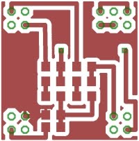
I knocked up a printed circuit board in Eagle...


A populated PCB is seen along with the original "Dolly" and the first completed clone in the photo below...


The unit is built into a (cheap version of a) Hammond 1590bb diecast enclosure, which I got on ebay from the "Fuzz Shack", who sells the enclosure as a kit with 1/4 inch jack sockets, a d.c. socket and 3pdt push-button switch at a good price (though I'm not using the switch - I've decided to stay with the original 'electronic' switching rather than go for "true bypass", so I'm using a different momentary action push-to-make foot-switch).

 The PCB and the wiring has to be carefully shoe-horned into the enclosure...


R.G.Keen says "The TS series seems to be at its best when driving the input to a tube amplifier" in his excellent discussion of the Tube Screamer circuit - I agree with him...


The two clones aren't both for me (although it is pretty convenient having two Tube Screamers with different set-ups dialled into each unit). Some lucky friend will find one in their Christmas stocking!

 ...-.- de m0xpd

Sunday, 28 October 2012

Dolly the Tube Screamer

All this talk of guitars set me thinking about the old days when, as a kid, I used to make replicas of my MXR Distortion Plus ...


Unlike most other areas of audio engineering, guitar amplification is NOT about sound reproduction - rather it is about sound production. The distinction is important; sound reproduction (as in monitoring and what was once called "Hi-Fi") is about generating a faithful acoustic representation of an electronic signal. Guitar amplification, in marked contrast, is part of the system creating the signal. The sound of the guitar amplifier is not (necessarily) at all neutral, introducing components of the overall sound that are important. Most important of these is the family of sounds when (particularly valve) amplifiers are pushed into overdrive, when the resulting distortion can have a pleasant, musical sound in the right context.

Recognition of this fact led to the production of effects pedals (like my old MXR, above) to create (or, at least, emulate) the sound without having to go to the inconvenience (and noise exposure) of over-driving an amplifier. It also led to the appearance of a whole lot of amplifier emulations, exemplified by those built into my new amplifier. Between these extremes of the early, simple distortion (or "fuzz") box and modern complex DSP emulations of classic amplifiers in overdrive there was a whole generation of more complicated distortion effects which I missed over the past few decades. I decided to "catch up" by making a clone of an Ibanez Tube Screamer - thus "Dolly" was born.

The Tube Screamer has three controls; "Drive", "Tone" and a final "Level" control, as seen on my cloned unit...


The schematic can be found at lots of sites over the 'net - start your search here. The most important part of the Tube Screamer (and many other distortion pedals) is the exploitation of the clipping effects of a pair of back-to-back diodes, as seen here in the "clipping" stage of my "clone"...


I used 1N4148 diodes and am (at present) using a TL072 op-amp (I'll change it for one of the original JRC4558s when I get round to making a final version).

Where the Tube Screamer is distinguished from other distortion pedals (including, for example, my old MXR) is in partnering the diode clipping section with filtering circuits - including an adjustable shelving HF section, giving lift or cut to high frequency components both of the original signal and of the harmonics generated by the clipping. The tone section and other aspects of the circuit are seen "round the back"...


Having made the unit, I thought I'd take the opportunity to show some waveforms illustrating its effect on a sinusoidal input (at 2kHz).

Here's the response of the device in "Bypass" mode (the original Tube Screamer has electronic "bypass" switching implemented by some n-channel FETS in a configuration I used before for the Tx audio mute of my Funster Plus rig) controlled by a push button (Dolly uses a 555 in a toggling bistable circuit, whereas the original uses a discrete flip-flop)...


Turning on the unit, with the "Drive" control on max (giving greatest clipping effect from the diodes) and the "Tone" on max (giving HF shelving boost) gives this response (in all the following images I adjusted the "Level" control to keep the output amplitude roughly constant)...


Rolling off the "Tone" to minimum, whilst keeping the "Drive" at maximum makes the waveform "smoother" - and has exactly the same effect on the sound...


Turning the "Drive" to minimum reduces the distortion effect, influencing the sound only when the guitar is played loudly - this sounds more like an amplifier close to its limit, being pushed over the edge into saturation only by the loudest signal components. It sounds nice!

With tone setting on "Max", the effect on the 2kHz sinewave is seen as a tendency toward a triangular wave...


Backing off the tone to minimum, all but removes the visible distortion of the 2kHz waveform...


In truth, all the sounds available from this clone of the Tube Screamer are pretty close to sounds already well-covered by the amplifier emulations built into my new Roland Cube amplifier - but it has been fun to clone Dolly. I might make a PCB and knock up a few copies for friends, just as I did in the old days!

 ...-.- de m0xpd

Sunday, 21 October 2012

Cube 40XL Footswitch

I came home from yesterday's G-QRP Mini Convention at Rishworth with (amongst other things) some pushbutton switches from Bowood...


intending to make a footswitch for my new Roland Cube 40XL guitar amplifier. The project was not quite as trivial as expected and other Cube owners may be interested to hear my findings. But first, a little background...

2012 has been for me thus far what Liz might call annus horribilis. Illness has robbed me of some of the energy and enthusiasm for leisure projects and work has been even more of a distraction than usual. Even the virtual organ project (Blogs Passim) has taken a back seat - it is upstairs and it requires that you sit up straight on the uncomfortable, hard bench - hardly the thing when you're not feeling 100%. I did, however, remember that there is one thing that a couch potato can do instead of watching (or even whilst watching) the idiot's lantern - play guitar!

I treated myself to a nice new guitar in celebration of this re-discovered pastime - a Peerless New York.

Then thoughts turned to amplifiers. I already have more than my fair share of guitars and amplifiers, but wanted something that included some of the interesting developments of the past few decades (on-board effects, "modelling" etc). I looked at Fender Super Champs, Line 6 Spiders and the Roland Cube 40XL. I settled on the latter, not least because I could make a simple footswitch to control the many features (rather than pay the manufacturer for one).

So, yesterday I started to knock up a trial footswitch, taking the chance to experiment with an idea for an "enclosure" made of scrap MDF. The piece of scrap that first came to hand was about right for three switches, so that's what I made...


Here's the circuit I used...


(I hope regular readers of this irregular blog will excuse the naive schematics in this post - this material might be of interest to other readers for whom electronics is not the vernacular).

The footswitch worked perfectly in controlling the Effects and Reverb. It also worked perfectly in switching between channels and selecting the alternative "Solo" settings. However, it refused to do anything in controlling the Delay / Looper functions - a particular disappointment as this was the feature I most urgently needed foot control for!

A quick sniff around the net led me to fellow radio amateur Steve, GW1XVC's excellent page on QRZ.com. Steve has also homebrewed a footswitch for the Cube 40XL and his switch works, as he proves in a video on YouTube. His QRZ page included the magic phrase "normally closed", describing the switches he used in his successful footswitch. Mine from Bowood (like all the other momentary action single pole switches in my junk boxes) are "normally open".

I tried "simulating" a normally closed switch (by holding down both switches and momentarily opening one of them) and - hey presto - the looper functions worked under control of my switches. So - I think I need to make an important announcement...

Owners of Roland's Excellent Cube XL amplifiers who, like me, are too cheap to buy expensive commercial footswitches, can use normally open switches for FX/Reverb and Channel/Solo functions BUT MUST USE NORMALLY CLOSED (/"PUSH TO BREAK") SWITCHES FOR THE DELAY/LOOPER functions. 

So - having got that off my chest, what do I do with the apparently useless normally open switches?

I measured the electrical behaviour at the footswitch sockets - open circuit, the control inputs sit at about +3.5V relative to the reference voltage on the sleeves of all the sockets (the footswitch inputs are on 1/4 inch Tip, Ring, Sleeve ('TRS') jack sockets - more commonly known as 'stereo' jacks). When shorted to the sleeve, a current of 450microAmps flows.

I could easily see how to control the looper with the required "normally closed" behaviour if I had some power available, but I didn't want to add a battery to complicate the footswitch - so I came up with a little twist to change the switching behaviour so as to emulate the "normally closed" function using a 2n3904 and a 10k resistor...


For those who don't know, both 2n3904 transistors and 10k resistors are widely available for less money than the switches.

The modified footswitch works perfectly. I just made the change on the two switches used for the Delay/Looper functions - the other switch on my prototype controls the Effects in "normally open" mode.

It works perfectly for me but now for the caveats:
  1. It hasn't been tested on another Cube 40XL, so I can't guarantee it will work perfectly for you and...
  2. It might not like the EMC-hostile conditions of live stage applications (but I'm sure that any issues could be resolved with a single additional capacitor for each transistor) and... 
  3. My footswitch wasn't designed to survive the violent attentions of thrash metal players in Jack Boots. Steve, GW1XVC's rugged construction is more equal to that task!  
Now I'm off to play some guitar

...-.- de m0xpd

Sunday, 1 July 2012

Teething Troubles with the Leslie

No sooner than I'd completed the modifications which turned my Leslie 125 into something approaching a 145, I ran into a problem...

Without warning, the amp popped its fuse. On investigation, it turned out to be the mains transformer. I could measure resistances of the order of tens of Ohms where there ought to be isolation - between the secondary, the primary and the core. Also, the secondary centre tap was no longer in the centre - in impedance, at least. Obviously, where once there was insulation there were now some conducting paths.

Maybe I've been lucky, but in 35+ years of tinkering with electronics, I never met a bad transformer before. They just work - or so I thought!

Just my luck - it is easy to find replacement transformers for a 122 or a 147 - they're stock items (especially in the US). But I couldn't find a source for a replacement for my 125 amp's transformer for love or money. Fortunately, Simon at BLS Electronics made me a new one, re-using the pressed steel shrouds from the old unit.

Here are the remains of the original, next to the new transformer...


Usual disclaimer - I don't know Simon or BLS Electronics from Adam - but they did a great job at a great price. The new transformer is now in place and everything was working fine until...

After having played though the newly restored speaker for best part of a day, I noticed that the lower rotor was creeping round in chorale. It would run in tremolo, but ground to a halt at the lower speed. I fiddled about and noticed that if I pushed up the rotor on its spindle (on which it is a friction fit), the rotor would turn again. But, after a few more hours, the old sluggish behaviour returned. Time to strip down the lower rotor...

Here's an exploded image of the rotor from the user's manual...


The drawing indicates that the bearing plate (#511-2 in the drawing above) is fixed in place from beneath the cabinet by two screws. I tilted the speaker enough to get a short screwdriver to the screws, but they didn't have any heads!

Instead, I saw the ends of the screws in some T-nuts. Despite expectations, the bearing unit in my 125 is fixed in from inside, on spacer blocks...


From what I could see, this is how it was made - no evidence of modifications of any kind. I could also quickly see what was slowing down the rotor - especially when it was "low" on the spindle. Here's the top of the bearing assembly, in the middle of which you see the grommet which goes through in the middle of the bearing (numbered 510-3 in the drawing from the user's manual)...


According to the user manual (see exploded drawing above) another grommet (513-2) at the bottom of the rotor bears on this grommet to support the weight of the rotor. Looking at the bottom of the rotor reveals that it had been scraping against the bearing housing, generating the drag that brought the whole assembly to a halt...


Also, I noticed that the bearing housing was distorted in such a way as to bring the bearing lower in the housing - adding to the possibility that the rotor grommet could foul on stationary parts. Look at the deformation in the lower housing component...


The fix was obvious - I needed to keep the rotor higher up the spindle, so the rubber grommet at the base was free. I took a "belt-and-braces" approach and made three interventions.

First, I cleaned and assembled the bearing, avoiding the distortion in the photo above, fractionally moving the ball race and its bearing surface higher.

Second, I inverted the grommet in the bearing, so its unworn lower part is now at the top...


Third, I added a washer between the grommet in the bearing and that on the rotor (between which there is no significant relative movement) to make double-sure there is real clearance between fixed and rotating parts.

The result? The speaker is transformed, with working chorale and much faster acceleration to tremolo. It has been running all day without a hint of trouble. I hope that has fixed it for good.

 I do have some outstanding jobs, most important of which is to cure a rattle/buzz coming from part of the rotor - there's a flared piece (made, I think, of expanded polystyrene) which is moving relative to the other wooden parts and - in so moving - buzzing. I've put some Blu Tack there as a temporary fix.


Excuse me - I must go back to the organ now - this speaker sounds SO good.

 ...-.- de m0xpd

Tuesday, 5 June 2012

Leslie 125 Modifications

Readers will be aware that I picked up an old Leslie 125 from ebay, just before Christmas. I always had plans for the speaker, but my hand was forced into action when it suddenly started to hum loudly and then popped its fuse - seemed a good cue for a rebuild of the amp and for the modifications I had in mind.

Here's the original speaker, nervously awaiting "surgery"...


My plan was to add a rotating horn, controlled by the MTCLogic speed controller, to take the speaker far from its humble origins to a baby 145. My purpose was two-fold; first to educate me in the ways of Leslies and second to avoid the expense of paying for a "real" 145 (the 125 cost me 31 pounds - you can't buy a 122, a 147 or a 145 for ten times that).

The most obvious external feature would be the additional "slots" in the top of the cabinet - so out came a router...


The result was pleasing enough - my compound cuts with two router bits made a passable impression of real louvres...


Whilst the sun still shone in the outdoor woodwork shop, I turned my attention to fitting some battens to hold the new top shelf. They were made from "available material" - the material having made itself available in a skip next to a building project -  I hate paying for lumber...


 With the battens in place, I could fit my new top shelf...


A little more modification gave me a pretty authentic back - with the original labels that proclaim the speaker's lowly origins as a 125...


Woodwork completed, I turned my attention to the electronics.

The can capacitor in the power supply filter was replaced, along with some other "mission-critical" capacitors and a power resistor in the power supply filter. There was also a capacitor missing in the amp - bypassing the output transformer's primary at HF and therefore (I suppose) important to HF stability of the circuit.

Also, I added a socket to take 240V and switched 240V to the speed control electronics...


 Here's the amp with its new socket on the side...


With the amp running again, I needed a crossover unit to divide the signal between the original 12 inch unit and the new horn. The stock Leslie crossover looks a bit ramshackle, being built up on a piece of hardboard...


I knocked up some brackets to mount the crossover safely on the side wall of the enclosure...


Also seen in the photo above is a (massively over-specified) 240 - 110V transformer, which I'm using to provide the US mains voltage for the MTCLogic speed controller. It is important that I keep this in "stock" condition, as this speaker will be a test-bed for my future work on the new speed control system.

The modified 125 sounds like a dream - it is a joy to use and a pleasure to look at! There are a few more jobs to do (like replacing that massive transformer with something more appropriate and making a motor cover for the top motor to seal the main enclosure), but its is so good to play that these details can wait!

My thanks to George Benton of Benton Electronics for his generosity in sourcing parts, his expertise and his friendship.

 ...-.- de m0xpd

Sunday, 18 March 2012

MICROCHIP disappointments

I have spent the last seven days frustrated by failures of MICROCHIP PIC devices.


I don't mean "failures" in the sense of heat and smoke. I don't mean "failures" in the sense of faulty logical operation (we didn't get that far). I mean "failures" in the sense of not doing what the manufacturer says it can do.

Before we start complaining, let's be clear - I am a fan of PICs. I have been using them since the 90s. As readers of this blog will know, I've used them in lots of radio-related projects (such as the multi-mode beacon) and more recently in the virtual organ. I've also used them "at work" and in real-world projects, most recently the MTCLogic controller. I am a fan and - perhaps - being a fan makes it all the more disappointing when things go bad...

It started with a 16F628A. I had found some old code on the 'net and, since it was written for the 628A, I thought I'd run it in that device. So I got a sample, only to be frustrated by it.

I found that I was completely unable to program the device using either my ICD2 or my PICKit2. [Incidentally, the claim that PICKit2 DOES support the 16F628A is made here (where it does remind users that debug is impossible without an additional component)]. Most of the time, I got a failure on verification at a very low address, suggesting that no programming had happened at all. Occasionally, a few locations verified before failure. Once (
in an afternoon trying to debug the issue) I got a successful programming.

Not good enough!

I could program the device in my PICStart Plus - but I have grown used to in-circuit serial programming and wanted to use it here. Besides, MICROCHIP and all their documentation and code (I'm using MPLAB 8.7) CLAIM that this is possible.

A quick look on the internet persuaded me that I'm not the only person who has fallen foul of this discrepancy between marketing claim and experienced engineering reality, so I gave up and ordered a more modern 18-pin device - the 16F88.

On delivery I found that the 16F88 was up for being programmed with either ICD2 or PICKit2. Great! Until I tried something else which is CLAIMED to be possible - using debug mode on the 16F88 with the PICKit2...

Once again, this doesn't work - most frequently in the following failure mode...


(occasionally I could get past that point, but the subsequent debug operation did not work). I looked on the 'net and - you guessed it - this is a known problem.

I didn't want to have to change device again, so I tried debugging with the ICD2. That works.

I don't mind failure per se. I do mind when somebody claims that it is possible to... when it simply is NOT possible to. I don't care if it once worked for somebody. All I care is that it did not work for me and has wasted my valuable time.

Time which is far too valuable to waste posing questions like "why change the name of timer 0's interrupt enable flag from the simple "T0IF" (12F675) to the wasteful, redundant "TMR0IF" (16F88)". I suppose I should be happy and contented by the fact that the 16F88 does manage to do (most of) what is claimed for it.

...-.- de m0xpd

Sunday, 11 March 2012

Volte-Face on Toner Transfer

Politicians do it all the time - so why shouldn't I? I've made a u-turn. A 180. A policy reversal.

I guess it really started this week, when I was trying to make up a little PCB for work - only about an inch square with a few SMT components on it...

However, it seemed to lie at the extreme edge of the abilities of my "Toner transfer" backyard PCB manufacturing technology (
blogs passim). It took me a couple of tries to produce a satisfactory batch of boards and I just don't have that much time to waste!

Fortunately, a mention on the G-QRP Yahoo Group this week had drawn my attention to a website, enticingly called "Blondihacks", produced by a talented engineer who rejoices in the name "Quinn Dunki". The particular link was to Quinn's description of PCB production, in which she summarises her methods for producing PCBs using pre-coated photosensitive boards. Quinn's descriptions and the frustrations of my week persuaded me to give it a try - so I ordered some board and developer from Rapid (who - once again - lived up to their name).

OK - here we go... Deep intake of breath... I hereby renounce Toner Transfer methods of PCB production. They may be cheap, but they are rubbish, compared to what can easily be achieved using photo methods. The quality of my first optical board comfortably exceeded anything I've ever made using toner transfer...


Don't waste your time with irons or laminators. Don't waste time trying to get rid of those irritating chalky deposits from glossy photo paper that get trapped between traces, that fill holes and that mess up fine detail. Don't waste time trying to use old magazines and suffer porosity in the etch resist and consequent discontinuities in the copper. Get yourself kitted out with some photographic technology. Do you detect a whiff of the zeal of the newly converted? That's me!

All I used for exposure was a UV-rich florescent tube intended for aquaria and an old picture frame. I'll work it all up into a "proper" light box eventually!

I didn't follow Quinn's advice about etching - my bubble-tank full of ferric chloride has never been a problem.

Incidentally, the PCB in question is a development environment for the MTCLogic controller - it replaces (by plugging into its DIL socket) the 12F657 PIC with a richer processor, with extra I/O and the luxury of a CCP module - just right for PWM applications...


As you see, there's MIDI input and output, an ICSP interface (here seen with an FCC68 adapter going to the ICD2, but equally at home plugged directly into my PICkit2), a couple extra analog inputs (by which system parameters can be adjusted using the prsets) and 4 digital inputs (to select options). As you gather, there are lots of exciting developments in hand on the Leslie controller front!

Incidentally, I like the way our American cousins say "a couple extra analog inputs...", as distinct from the English equivalent "a couple OF extra analog inputs...".

Do yourself a favour - get yourself down to Blondihacks for some well crafted, witty American writing surrounding some interesting and educational projects.

Do yourself another favour - ignore any previous advice seen on these pages advocating toner transfer.

Anyone want a knackered laminator?
...-.- de m0xpd