Saturday, 6 August 2011

Gyrator Analysis 2

Recently I posted an analysis of a circuit called a "Gyrator" - only to realize that it was wrong! I'm interested in the gyrator having used it in a design for an active CW Filter, recently published in SPRAT.

Fortunately, I spotted my mistake before suffering the indignity of having somebody point it out and I updated the original post with a warning that the so-called "analysis" was nonsense. I also promised to correct it - so here we go...

The circuit under consideration is shown in the image below...

We start the analysis by noting that the voltage at the non-inverting input to the op-amp can be related to the input voltage using the potential divider equation (it was at this stage I made one of the dumb mistakes in my previous botched analysis)...


Ideal operation of the op-amp (which here is set up as a voltage follower) will force the voltage difference between the inputs to zero, such that...
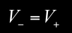

We're now ready to solve for the two currents i1 and i2 – we start with i1


Substituting for the voltage at the non-inverting input gives...


(Microsoft's Equation Editor has done a pretty poor job of laying out this equation - but life is rather too short to do anything about it!!)

Next we turn our attention to i2
...


Now we have both currents, we're able to solve for the input impedance of the circuit ...


which is solved by substituting our solutions for the two currents...


A little boring algebraic manipulation gives...


and a little more yields a more useful form for the "final" result...


This impedance is that of a series combination of resistor and inductor, with another resistor "shunting" the inductor, as shown in this equivalent circuit...


The Gyrator is seen to emulate a "virtual inductor" having value L = (R2-R1)R1C, in series with a resistor Rs = R1, shunted by a resistor Rshunt=R2-R1. This virtual inductor can easily have large value - a value so high as to be impractical to achieve using a physical inductor.

Simplistic descriptions of the Gyrator have an approximate solution for the "virtual inductor" (which is the same as that presented in my erroneous "analysis") but miss the shunt resistance. In practical cases, R2 >> R1, such that the simple solution is a very good approximation of the correct analysis presented here. But that's no excuse - an analysis (even one published in such informal surroundings as this blog) must be right.

QED Hi Hi

...-.- de m0xpd

Monday, 25 July 2011

Slightly more organized

My work has been making unusually high intrusions into the more important aspects of life recently, with the pressures of moving to new premises and trips to The Netherlands and Italy in the last two weeks. Although little has been achieved in matters which might interest you, dear reader, I have at least been able to move slightly forward on the Virtual Organ (Blogs passim)...


Specifically, the organ has acquired another set of Hammond drawbars (giving me a full complement of 9 drawbars for each of the swell and great manuals), a dedicated PC and an old monitor.

This past weekend, I finally got round to transferring the main controller (in which a PIC16f873 reads all the drawbars and switches and sends their settings to the PC over MIDI) from a solderless breadboard to a couple of PCBs...


The main controller board still has a 16*2 display, which one day will move from the board to a visible position on the outer case of the organ. There is also a separate "decode" board, made to correct my own stupidity in not incorporating sufficient decoding on the drawbar interface boards (the action of which is described here), one of which is seen in the photo above.

Also visible in the photo are a couple of small boards which provide interface to assorted analog controls (at the moment, potentiometers for percussion and key-click level). These boards also interface to switches but this is a waste for simple "Boolean" controls - one day I'll use the matrix interface I've built into the new controller board to read the switch settings.

The photo below shows the organ in a corner of the shack, with the software running in the new small form factor PC I "won" on eBay just for this project.


The pedal-board "woodwork" needs completing - in fact the entire organ needs a new enclosure. Still - at least it is now working, playable and self-contained. Next task is to sort out the bug in the new PC which is making it very difficult to turn on (without apparently random resets, visits to "Safe Mode" etc). Perhaps I should have relied on traditional tone-wheel technology rather than a computer!

...-.- de m0xpd

Sunday, 17 July 2011

Bit Set - or not

I've been playing with a simple PWM application on PICs...

The final application will use an 8-pin PIC (the 12F675) but I chose to start code development on the 16F676, partly because I had some in the junk bin and mainly because I also had the special 20-pin PIC16F676-ICD device which allowed me to do debugging (I'm too cheap to buy the PIC12F675-ICD).

All was working FB until I tried to translate the code to the 12F675 - I had one of my two PWM signals running, but couldn't get the second to appear on the appropriate I/O line, no matter what I tried.

Here's what turned out to be the offending lines of code...


It is part of the interrupt service routine, which establishes the two (phase-opposed) PWM signals on GPIO pins 1 and 2. The signal on GPIO2 was fine, but there was nothing but a glitch on GPIO1.

Can you see anything wrong with the code? I couldn't - despite staring at it for an hour!

I assumed that I'd made a mess of setting up the GPIO port and spent ages staring at different pieces of the program and making changes just out of desperation. Everything appeared logically consistent and I just couldn't see where I'd gone wrong.

Eventually, I searched for anybody else who'd suffered the indignity of PICs behaving badly.

Fortunately some Kiwis have trodden this path before me and written it up .

It seems you can't just perform bit-wise operations (like bit-set or bit-clear) on the port of the 12F675 without errors (perhaps I should say without "unexpected results"), despite the fact that you can on other PICs - like the 16F676 on which I did my code development!

The fix is simple - don't use bit-wise manipulations...


I feel a little better that I couldn't see a logical error in the code (there wasn't one) but the fact that the 12F675 "doesn't obey its own instructions" still galls!

...-.- de m0xpd

Tuesday, 5 July 2011

Gyrator analysis


Your humble servant's article in this spring's number of SPRAT (pp 20 - 23), "A(nother) CW Filter", uses a circuit called a Gyrator to implement an inductive impedance. I was thinking ahead to a scheduled talk on the CW Filter at the Warrington club and realized it would be nice (that is to say "it would please me") to include an analysis of the gyrator.

This is a pretty standard circuit configuration, but a quick Google ((v) search the internet (for information) using the Google search engine) revealed that such analyses aren't exactly falling over one another - so here's the m0xpd story...

The circuit in question is shown below...


The voltage at the non-inverting input to the op-amp is related to the input voltage by the potential divider equation:


Ideal action of the op-amp (which is configured as a voltage follower) is summarised by:


We're now in a position to identify the currents i1 and i2 - we start with i1...


Substituting for the voltage at the non-inverting input gives (with apologies for the contribution of the "Microsoft Equation 3.0" equation editor):


i2 is simpler:


The input impedance to the circuit is:


which is solved by substituting for the two currents above...


There (in the box) it is!

The input impedance is the series combination of a resistor and a "virtual" inductor (in the sense that an inductor presents a positive reactance, proportional to frequency), with the inductor taking the value of the product of the two resistances and the capacitance...


Next time you need a big coil, try one of these instead!

...-.- de m0xpd

Friday, 17 June 2011

That's just swell

A few otherwise idle moments were used fitting the swell / expression pedal from the old Hammond Organ Donor into my virtual organ project (Blogs passim).

Here's the swell pedal, complete with a nice patina of rust...


I put out a cri-de-coeur a few weeks back in this blog and on the Organ Forum, asking for any information on Hammond Swell pedals, but attracted a null response. Fortunately a new Texan friend gave me some advice and put me on the right track.

The pedal has a light source (an ordinary incandescent bulb) and a light-dependant resistor. There is a tapered shutter (implemented on a piece of fibreglass PCB) which moves with the pedal and stops down the light reaching the LDR. The key components are visible here...


I tried to measure the resistance of the unit as a function of pedal angle - with mixed results. Here's a graph, which reveals an approximately logarithmic taper (as you might expect, given that the pedal originally implemented an audio volume control function). Unfortunately, the resistance went out of range of the meter I used as I got close to the 0 degrees (i.e. fully depressed) position. Still, the graph has taught us its lesson...


I originally had planned to connect the pedal to one of the analog inputs implemented on the main controller - but it occurred to me that I could interface to the separate pedal controller instead.

This had the advantage of physical proximity to the swell pedal, making a completely stand-alone pedal unit. The disadvantage was the fact that the pedal controller had, to date, no existing analog interface. What's more, the only available I/O line on the PIC 16F676 was not one of those that could be set up as an analog input. Accordingly, I had to make a complete re-work of the pedal controller. This gave me chance to add a stabilized power supply for the swell pedal's bulb (which draws about 180 mA at the 5V operating point I've chosen).

Here's a schematic of the revised pedal controller...


and here's the finished system (with the bulb regulator sporting an old TO3 heatsink from the junkbox)...


You can see the additional connectors to provide power to the bulb and to sense the pedal resistance.

It works very well - but the logarithmic taper makes the expression control (too) non-linear. I need to implement a look-up table in the software to undo the log taper - but that will have to wait until the next otherwise idle moment!

...-.- de m0xpd

Sunday, 5 June 2011

SSDRA, another Dipper, and Red Roses

EUREKA - I have found a copy of Solid State Design for the Radio Amateur - for just a pound!


I spent an hour at West Manchester's Annual "Red Rose" QRP Rally today - which is where I made my purchase of the classic by Hayward and DeMaw. It is a paperback edition and it is a little tatty - but complete. A genuine bargain!

On the same stall, I spotted another Dipper, which I snapped up (this time for four pounds), thinking I might use the coils with the Heathkit unit I won in a WARC raffle a few weeks back.


However, on testing the device, I found it very sensitive, beating both my g3wpo and my GD-1u raffle win, so I shalln't be stealing away the coils.

Here's the new dipper...


It is powered by a PP3, has one active device (a four-pin metal can carrying the (partial) number 2089 - or is it 7089) which I don't recognise and is either an excellent piece of homebrew or a nicely executed kit. There are no identifying marks of any kind - so if you can tell me anything about it, I'd love to know!

I replenished stocks of some boring items from Will at Bowood, stopped by at the Kanga, RSGB and (of course) G-QRP stalls and took my leave of this excellent rally. I will certainly return next year and encourage all within striking distance to do the same.

...-.- de m0xpd

Saturday, 4 June 2011

m0xpd/mm

Just back from a(nother) sailing trip on the Westerly Discus CC sloop "Beatrice Rose", with owner Neil and fellow crew member Paul...


This voyage took us from Beatrice Rose's home port of Southsea Marina to Lymington, Poole, Portland, Yarmouth, Newtown Creek, Folly Reach (R. Medina) and back to Southsea. We logged 195 miles, 95% of which was sailing close-hauled to windward.

The opening weekend saw foul weather (in which an 11m yacht was lost), some of which we sat out for a day in Lymington after becoming bored beating into a Force 7 through the Solent. During that enforced rest, I took out the FT817 in the hope of making some CW QSOs as m0xpd/mm, but discovered that Berthon, Lymington (in common with most other marinas) is QRM hell (there are lots of noisy inverters etc on boats) and 40m was s9 +10dB of solid, ugly noise.

VERY unusually, I had also packed the FT817's microphone, so I switched to 2 metres and answered a shout from Rob, g6bdv. Rob was on a cliff-top above the Needles (the conspicuous rocks at the western tip of the Isle of Wight) and reported 50 miles-an-hour wind gusts at that exposed location. Here's a photo of Rob's location which I took a few days later as we passed on our (engine assisted) run east from Portland - in rather calmer conditions!


We shared Poole Quay with a pretty brace of tall ships: the Sea Cadets' Training Ship "Royalist"...


and another brig, "Øilleleje"...


Later, after a night in the new marina associated with next year's Olympic sailing events at Portland and a visit to Yarmouth, which was appropriately dressed for the visit of the Old Gaffers this weekend...


we spent a night on a buoy in the idyllic Newtown Creek (here seen with shoal draft boats moored close to the "Conspicuous Black Boathouse")...


At last, I had escaped the buzz and drone of the boaties' QRM and could enjoy some real (i.e. CW) QSOs - most notably with Fred, dl4zby, nr Frankfurt.

A terrific trip - which landed me back ashore in time for tomorrow's Red Rose QRP Festival. Thanks, Neil!

...-.- de m0xpd(/mm)