A couple of posts ago I wrote "I'll have something to say about adding and 'mixing' harmonics; watch this space."
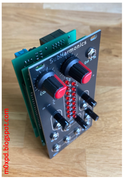
Well, the time has come - enter my new module, SubHarmonics
Before I go any further, I ought to explain what sub-harmonics are and why I might waste time and money developing some electronics which generates and manipulates them.
You will have heard of 'harmonics'; the idea that any periodic signal is composed of (a d.c. component plus) a sum of terms having frequencies at integer multiples of the 'fundamental frequency', where the fundamental frequency is the reciprocal of the period.
This concept, which is the core of Fourier analysis, underpins some of the most important mathematical and computational constructs of our age, including the Fast Fourier Transform. It also explains the "Harmonic series" of musical notes: those notes some of which can be sounded on a natural trumpet (/bugle) or trombone (excepting 'pedal notes'), a string, etc.
It is possible to construct another series of frequencies starting on a fundamental which, instead of having members whose frequencies are integer multiples of the fundamental frequency (f0, 2f0, 3f0, 4f0, ...), has members whose frequencies are integer quotients of the fundamental (f0, f0/2, f0/3, f0/4 ...). This is called the undertone series or sub-harmonic series.
Why does the sub-harmonic series matter musically?
Well, one of my sons-in-law plays bass and (as if his bass isn't low enough already) he likes to add an "octave down" effect

to add sound an octave lower - a sub-harmonic. So, sub-harmonics can add bass - but they are not just used to add weight and "depth".
Since two different sub-harmonics of a common fundamental are harmonically related they can be combined to represent harmony - this is the main reason for my interest.
Two distinct sub-harmonics occur at a frequency ratio of m/n where m and n are small integers. This "ratio of small integers" is the "recipe" for a musical interval (an octave is 2/1, a fifth is 3/2, a fourth is 4/3, etc) - making the combination of two sub-harmonics (often - but not always) musically useful.
That's the background - now back to the electronics:
My module "SubHarmonics" takes a fundamental signal, 'X', which is either generated by the module's internal Voltage Controlled Oscillator or derived from an external signal applied to the "Ext X In" clock input, and generates two square-wave signals, 'A' and 'B'.
These signals A and B are sub-harmonics of X (that is to say, their frequency is a quotient resulting from dividing the frequency of X by an integer divisor) and each divisor is set either by a front panel control on "SubHarmonics" or by a Control Voltage applied to the relevant control input.
You can see the divisor controls, CV inputs and indicators on the front panel:

The divisors can be set between 2 and 18, giving the unit a range a little over four octaves.
The two sub-harmonics are available individually as outputs and they are also applied to two internal modulators which combine A and B through switching equivalents of 'amplitude modulation' and 'ring modulation'. The result of these two modulators is passed to a voltage-controlled crossfader circuit to produce the module's fourth output: a "modulation mix".

The signal on this "modulation mix" output can be either of the two modulation types or a mix of the two.
The 'scope screenshots below show the module in action. There is an example of the 'ring modulation', implemented by an XOR operation between A and B (when the Mix control is at minimum, 0V level), left, and the 'amplitude modulation', implemented by an OR operation between A and B (when the Mix control is at maximum, 5V level), right.
I explained (at very tedious length) how and why modulation by OR gates produces an output identical (in terms of magnitude Fourier Transform) to modulation by AND gates for the particular case of "antipalindromic" inputs in an earlier post; these A and B sub-harmonics are antipalindromic.

The fundamental, X is the top trace in yellow - it is at approximately 600Hz. The first sub-harmonic, A, is the second trace, in Cyan. It is associated with the divisor m := fx/fA = 6 (giving the sub-harmonic at 100Hz). The second sub-harmonic is the third trace, in Magenta. It is associated with the divisor n := fx/fA = 12 (giving the sub-harmonic at 50Hz). The X, A and B traces are the same in the plots above.
However, changing the Mix setting changes the fourth trace, the Mod Mix output shown in Blue. It will be noted that the Mod Mix output is actually inverted; it goes from 0V to a negative value (I had no spare op-amp stages to correct this and no more space on an already busy board!)
In the left hand scope screen above, the Blue trace can be seen to describe the inverted exclusive OR on A, B. In the right hand scope screen above, the Blue trace describes the inverted XOR on A,B.
This inversion is performed in analog (by the action of the cross-fader), but it is (in this case) working as a perfect logical complement (making inverted OR look like NOR etc). Things are more complicated when the Mix control is at an intermediate setting:

Here, (above) with the X, A and B signals as before, the Mod Mix output (bottom, Blue trace) is seen to have a more complex waveform, mixing together elements of the balanced and unbalanced modulated signals from the two extreme cases illustrated above; the crossfader works!
In use, setting the 'Mix' control at the lowest setting gives the clean 'ring modulated' sound and increasing the 'Mix' setting increases the complexity of the sound toward the richness (/harshness) of the simple product of A and B.
The beauty of "SubHarmonics" is the ease with which a single pitch signal can generate a tone (or a 'melody') and the module can then fill out this single line with not just two sub-harmonics, but with a rich, inter-modulated texture.
Everything about the module is dynamic, being controllable by external control voltages, which can come from sequencers, LFOs or random generators, to give an infinite variety of expression.
The system is implemented largely in CMOS logic on two PCBs. The internal VCO uses the core of Moritz Klein's 'Shapes VCO', (later used as the Erica Synths mki x es.edu VCO), which fits nicely with the CMOS environment and is a very stable, elegant design - like all Moritz's work. The crossfader uses half an LM13700 OTA and the controls and CV inputs for the divisors are read and decoded by a PIC 16F676.


into the finished "SubHarmonics" module -


No comments:
Post a Comment